Toshiba 32HLX95 Owners Manual - Page 19
Connecting a DVD player with ColorStream, component video and a VCR
 |
View all Toshiba 32HLX95 manuals
Add to My Manuals
Save this manual to your list of manuals |
Page 19 highlights
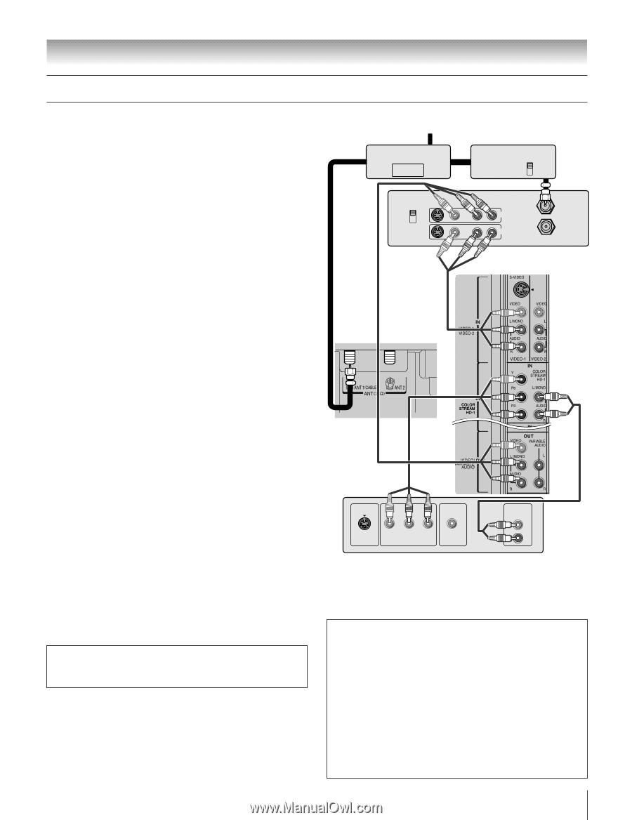
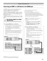
Chapter 2: Connecting your TV Connecting a DVD player with ColorStream® (component video) and a VCR Your TV has ColorStream® (component video) inputs. You will need: one signal splitter three coaxial cables two sets of standard A/V cables • For better picture performance, if your VCR has S-video, use an Svideo cable (plus the audio cables) instead of the standard video cable. However, do not connect both types of video cable to VIDEO 1 at the same time or the picture performance will be unacceptable. • If you have a mono VCR, connect L/MONO on the TV (VIDEO 1) to your VCR's audio out terminal using the white audio cable only. one pair of standard audio cables one set of component video cables • You can connect the component video cables (plus audio cables) from the external DVD player to either set of ColorStream HD terminals on the TV (HD 1 or HD 2). The ColorStream HD 1 and HD 2 terminals can be used with Progressive (480p, 720p) and Interlaced (480i, 1080i) scan systems. A 1080i signal will provide the best picture performance. • If your DVD player has HDMI video, see page 21. To view antenna or Cable channels: Turn OFF the VCR. Select the ANT 1 video input source on the TV.* To view the DVD player: Turn ON the DVD player. Select the ColorStream HD 1 video input source on the TV.* To view the VCR: Turn ON the VCR. Select the VIDEO 1 video input source on the TV.* To record a TV program while watching a DVD: Turn ON the VCR. Tune the VCR to the channel to record. Select the ColorStream HD 1 video input source on the TV* to view the DVD. To select the video input source, press INPUT on the remote control (see page 60). To program the TV remote control to operate other devices, see Chapter 3. The unauthorized recording, use, distribution, or revision of television programs, videotapes, DVDs, and other materials is prohibited under the Copyright Laws of the United States and other countries, and may subject you to civil and criminal liability. From antenna or Cable Signal splitter OUT CH 3 CH 4 IN OUT VIDEO Cable box IN CH 3 CH 4 OUT Stereo VCR AUDIO LR IN OUT LR IN from ANT OUT to TV TV upper back panel TV lower back panel DVD player with component video Y PB PR S-VIDEO COMPONENT VIDEO OUT VIDEO OUT AUDIO OUT L R Note: The VIDEO/AUDIO OUT terminals output signals from the ANT 1, ANT 2, VIDEO 1, and VIDEO 2 terminals when the appropriate input mode is selected. The playing disc's contents by the DVD section are not output. To use the TV Guide On Screen™ recording features: 1. Connect the G-LINK™ cable according to the instructions on page 23. 2. Make sure the VCR is connected to the A/V OUT terminals on the TV (see illustration). 3. Set the VCR to the appropriate line input (refer to your VCR owner's manual for details), and then turn OFF the VCR. 4. See Chapter 5 for details on setting up the TV Guide On Screen™ system. 5. See Chapter 7 for details on using the TV Guide On Screen™ system. Copyright © 2005 TOSHIBA CORPORATION. All rights reserved. 19
-
 1
1 -
2
-
3
-
4
-
5
-
6
-
7
-
8
-
9
-
10
-
11
-
12
-
13
-
 14
14 -
 15
15 -
 16
16 -
 17
17 -
 18
18 -
 19
19 -
 20
20 -
 21
21 -
 22
22 -
 23
23 -
 24
24 -
25
-
26
-
27
-
28
-
29
-
30
-
31
-
32
-
33
-
34
-
35
-
36
-
37
-
38
-
39
-
40
-
41
-
42
-
43
-
44
-
45
-
46
-
47
-
48
-
49
-
50
-
51
-
52
-
53
-
54
-
55
-
56
-
57
-
58
-
59
-
60
-
61
-
62
-
63
-
64
-
65
-
66
-
67
-
68
-
69
-
70
-
71
-
72
-
73
-
74
-
75
-
76
-
77
-
78
-
79
-
80
-
81
-
82
-
83
-
84
-
85
-
86
-
87
-
88
-
89
-
90
-
91
-
92
-
93
-
94
-
95
-
96
-
97
-
98
-
99
-
100
-
101
-
102
 |
 |