Toshiba 52HM95 Owner's Manual - English - Page 10
TV back panel connections - hd tv
 |
UPC - 022265251157
View all Toshiba 52HM95 manuals
Add to My Manuals
Save this manual to your list of manuals |
Page 10 highlights
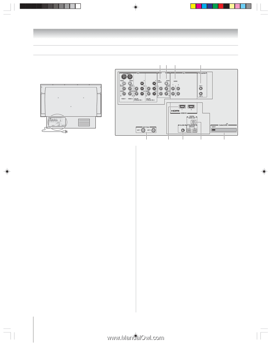
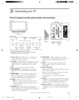
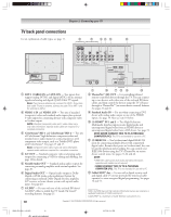
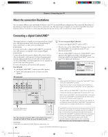
Chapter 2: Connecting your TV TV back panel connections For an explanation of cable types, see page 11. 2 3 54 9 8 OUT } } { OUT 1 ANT-1 (CABLE) IN and ANT-2 IN - Two inputs that support analog (NTSC) and digital (ATSC) off-air antenna signals and analog and digital (QAM) Cable TV signals. Note: If you have an antenna only, connect it to ANT-1. If you have both cable TV and an antenna, connect the cable TV to ANT-1 and the antenna to ANT-2. 2 VIDEO 1 IN and VIDEO 2 IN - Two sets of standard (composite) video and standard audio inputs plus optional S-video inputs for connecting devices with composite video or S-video output. NOTE: Standard (composite) video and S-video cables carry only video information; separate audio cables are required for a complete connection. 3 ColorStream® HD-1 and ColorStream® HD-2 - Two sets of ColorStream® high-definition component video and standard stereo audio inputs for connecting devices with component video output, such as a Toshiba DVD player with ColorStream®. See pages 15 and 17. Note: Component video cables carry only video information; separate audio cables are required for a complete connection. 4 A/V OUT - Standard composite video and analog audio outputs for connecting a VCR for editing and dubbing. See page 18 for details. 5 Variable Audio OUT - Standard analog audio outputs for connecting an analog amplifier with external speakers. See page 20. 6 Digital Audio OUT - Optical audio output in Dolby Digital or PCM (pulse-code modulation) format for connecting an external Dolby Digital decoder, amplifier, A/V receiver, or home theater system with optical audio input. See page 20. 7 G-LINK® - For use with one of the enclosed IR blaster/ G-LINK® cables to enable the TV Guide On Screen® recording features. See page 25. 1 0 7 !¡ 6 !™ 8 TheaterNet™ (IR) OUT - For controlling infrared remote-controlled devices through the TV. You can connect up to two devices with either one of the enclosed IR blaster cables, and then control the devices using the TV's IR passthrough or TheaterNet™ (on-screen device control) features. See pages 21 and 45. 9 Standard Audio IN - For use when connecting a DVI device with analog audio output to one of the HDMI inputs. See page 19. Also see item 10 below. 0 (2) HDMI™ IN 1 and 2 - Two High-Definition Multimedia Interface inputs receive digital audio and uncompressed digital video from an HDMI device or uncompressed digital video from a DVI device. See page 19. NOTE: NEVER CONNECT THIS TV TO A PERSONAL COMPUTER (PC). This TV is not intended for use with a PC. !¡ (2) IEEE1394 - Two bi-directional digital IEEE1394 ports for connecting multiple devices with compressed digital video. Because these ports are bi-directional, they can be used for playback and recording. You can control your IEEE1394 devices using the TV's TheaterNet on-screen device control icons. See pages 21-24 and 46. NOTE: • IEEE1394 cable carries both audio and video information; separate audio cables are not required. • NEVER CONNECT THIS TV TO A PERSONAL COMPUTER (PC). This TV is not intended for use with a PC. !™ CableCARD™ slot - For use with a digital security card and digital cable TV service (provided by your local cable operator) to view encrypted digital programming. See pages 12 and 51. ___________ HDMI, the HDMI logo and High-Definition Multimedia Interface are trademarks or registered trademarks of HDMI Licensing LLC. CableCARD™ is a trademark of Cable Television Laboratories, Inc. 10 Copyright © 2005 TOSHIBA CORPORATION. All rights reserved. HM95_R2_009-11_061505 10 6/27/05, 6:44 PM
-
 1
1 -
2
-
3
-
4
-
 5
5 -
 6
6 -
 7
7 -
 8
8 -
 9
9 -
 10
10 -
 11
11 -
 12
12 -
 13
13 -
 14
14 -
 15
15 -
16
-
17
-
18
-
19
-
20
-
21
-
22
-
23
-
24
-
25
-
26
-
27
-
28
-
29
-
30
-
31
-
32
-
33
-
34
-
35
-
36
-
37
-
38
-
39
-
40
-
41
-
42
-
43
-
44
-
45
-
46
-
47
-
48
-
49
-
50
-
51
-
52
-
53
-
54
-
55
-
56
-
57
-
58
-
59
-
60
-
61
-
62
-
63
-
64
-
65
-
66
-
67
-
68
-
69
-
70
-
71
-
72
-
73
-
74
-
75
-
76
-
77
-
78
-
79
-
80
-
81
-
82
-
83
-
84
-
85
-
86
-
87
-
88
-
89
-
90
-
91
-
92
-
93
-
94
-
95
-
96
-
97
-
98
-
99
-
100
-
101
-
102
-
103
-
104
-
105
-
106
-
107
-
108
-
109
-
110
-
111
-
112
 |
 |