ZyXEL VES1724-56B2 User Guide - Page 113
VDSL Line Profile Setup > RFI Band
 |
View all ZyXEL VES1724-56B2 manuals
Add to My Manuals
Save this manual to your list of manuals |
Page 113 highlights
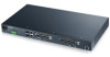
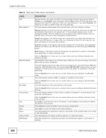
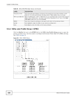
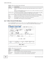
Chapter 9 VDSL Setup The following table describes the labels in this screen. Table 37 VDSL DPBO Setup LABEL DESCRIPTION DPBOESEL DPBOESCMA, DPBOESCMB, DPBOESCMC DPBOMUS DPBOFMIN DPBOFMAX DPBOEPSD Specify the electrical length of the cable between the Switch and CPE devices. See UPBO/DPBO Electrical Length on page 100. These parameters define a cable model that is used to describe the frequency dependent loss of exchange-side cables. This defines the assumed minimum usable receives PSD mask (in dBm/Hz) for exchange based services, used to modify parameter DPBOFMAX defined below. Enter from 0 to -127.5 dBm/Hz in steps of 0.5 dB. This defines the minimum frequency from which the DPBO shall be applied. Enter from 0 kHz to 8832 kHz in steps of 4.3125 kHz. This defines the maximum frequency at which DPBO may be applied. Enter from 138 kHz to 29997.75 kHz in steps of 4.3125 kHz. DPBOEPSD (Assumed Exchange PSD Mask) defines the PSD mask that is assumed to be exchanged at CO. Use this graph to view PSD level to frequency relationship. The horizontal is frequency in MHz and vertical is power level in dBm/Hz. Click Custom to have the breakpoints and PSD levels configured in the bottom of the screen updated to this DPBOEPSD graph. DPBOESEL Break Point Tone Index Alternatively, you can click one of the others (CAB_ANSI, EX_ANSI, CO_PSD, CAB_ETSI, EX_ETSI, Flat_PSD) to use a pre-defined PSD mask. Specify the electrical length of the cable between the Switch and CPE. See UPBO/DPBO Electrical Length on page 100. This index number identifies each incremental break point. A tone is a sub-channel of a VDSL band. DMT divides VDSL bands into many 4.3125 kHz tones. Frequency (kHz) PSD level (dBm/Hz) Modify Cancel Clear Enter an increased number (than previous row) from 0 to 4096 in this field that is also the horizontal of the DPBOEPSD graph. This read-only field displays a frequency that equals the tone index multiple 4.3125 dBm/Hz. This field automatically calculates after a Tone Index value is entered. Enter the PSD level for the Y-axis of DPBOEPSD graph. Click this to save the settings to the Switch and return to the previous screen. Click Cancel to reset the fields to your previous configuration. Click Clear to clear the fields to the factory defaults. 9.3.5 VDSL Line Profile Setup > RFI Band Click the Modify link next to the RFI BAND field in the VDSL Line Profile Setup screen to open the screen as shown next. Use this screen to specify the RFI bands through which the Switch and VES1724-56 User's Guide 113
-
 1
1 -
2
-
3
-
4
-
5
-
6
-
7
-
8
-
9
-
10
-
11
-
12
-
13
-
14
-
15
-
16
-
17
-
18
-
19
-
20
-
21
-
22
-
23
-
24
-
25
-
26
-
27
-
28
-
29
-
30
-
31
-
32
-
33
-
34
-
35
-
36
-
37
-
38
-
39
-
40
-
41
-
42
-
43
-
44
-
45
-
46
-
47
-
48
-
49
-
50
-
51
-
52
-
53
-
54
-
55
-
56
-
57
-
58
-
59
-
60
-
61
-
62
-
63
-
64
-
65
-
66
-
67
-
68
-
69
-
70
-
71
-
72
-
73
-
74
-
75
-
76
-
77
-
78
-
79
-
80
-
81
-
82
-
83
-
84
-
85
-
86
-
87
-
88
-
89
-
90
-
91
-
92
-
93
-
94
-
95
-
96
-
97
-
98
-
99
-
100
-
101
-
102
-
103
-
104
-
105
-
106
-
107
-
 108
108 -
 109
109 -
 110
110 -
 111
111 -
 112
112 -
 113
113 -
 114
114 -
 115
115 -
 116
116 -
 117
117 -
 118
118 -
119
-
120
-
121
-
122
-
123
-
124
-
125
-
126
-
127
-
128
-
129
-
130
-
131
-
132
-
133
-
134
-
135
-
136
-
137
-
138
-
139
-
140
-
141
-
142
-
143
-
144
-
145
-
146
-
147
-
148
-
149
-
150
-
151
-
152
-
153
-
154
-
155
-
156
-
157
-
158
-
159
-
160
-
161
-
162
-
163
-
164
-
165
-
166
-
167
-
168
-
169
-
170
-
171
-
172
-
173
-
174
-
175
-
176
-
177
-
178
-
179
-
180
-
181
-
182
-
183
-
184
-
185
-
186
-
187
-
188
-
189
-
190
-
191
-
192
-
193
-
194
-
195
-
196
-
197
-
198
-
199
-
200
-
201
-
202
-
203
-
204
-
205
-
206
-
207
-
208
-
209
-
210
-
211
-
212
-
213
-
214
-
215
-
216
-
217
-
218
-
219
-
220
-
221
-
222
-
223
-
224
-
225
-
226
-
227
-
228
-
229
-
230
-
231
-
232
-
233
-
234
-
235
-
236
-
237
-
238
-
239
-
240
-
241
-
242
-
243
-
244
-
245
-
246
-
247
-
248
-
249
-
250
-
251
-
252
-
253
-
254
-
255
-
256
-
257
-
258
-
259
-
260
-
261
-
262
-
263
-
264
-
265
-
266
-
267
-
268
-
269
-
270
-
271
-
272
-
273
-
274
-
275
-
276
-
277
-
278
-
279
-
280
-
281
-
282
-
283
-
284
-
285
-
286
-
287
-
288
-
289
-
290
-
291
-
292
-
293
-
294
-
295
-
296
-
297
-
298
-
299
-
300
-
301
-
302
-
303
-
304
-
305
-
306
-
307
-
308
-
309
-
310
-
311
-
312
-
313
-
314
-
315
-
316
-
317
-
318
-
319
-
320
-
321
-
322
-
323
-
324
-
325
-
326
-
327
-
328
-
329
-
330
-
331
-
332
-
333
-
334
-
335
-
336
-
337
-
338
-
339
-
340
-
341
-
342
-
343
-
344
-
345
-
346
-
347
-
348
-
349
-
350
-
351
-
352
-
353
-
354
-
355
-
356
-
357
-
358
-
359
-
360
-
361
-
362
-
363
-
364
-
365
-
366
-
367
-
368
-
369
-
370
-
371
-
372
-
373
-
374
-
375
-
376
-
377
-
378
-
379
-
380
-
381
-
382
-
383
-
384
-
385
-
386
-
387
-
388
-
389
-
390
-
391
-
392
-
393
-
394
-
395
-
396
-
397
-
398
-
399
-
400
-
401
-
402
-
403
-
404
-
405
-
406
-
407
-
408
-
409
-
410
-
411
-
412
-
413
-
414
 |
 |
