ZyXEL VES1724-56B2 User Guide - Page 98
VDSL2 Profiles, Con d Versus Actual Rate, Impulse Noise Protection INP
 |
View all ZyXEL VES1724-56B2 manuals
Add to My Manuals
Save this manual to your list of manuals |
Page 98 highlights
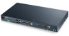
Chapter 9 VDSL Setup VDSL2 Profiles Eight VDSL2 frequency profiles (8a, 8b, 8c, 8d, 12a, 12b, 17a, and 30a) are defined in G.993.2. They are based on each annex specifying spectral characters (Annexes A, B and C). Each profile covers certain settings and parameters, such as maximum aggregate transmit power. The higherfrequency profiles (17a and 30a) are mostly used to deliver high speed at shorter distances. Note: At the time of writing, the Switch supports the Annex A with 8a, 8b, 8c, 8d, 12a, 12b, 17a, and 30a. The following table summarizes the VDSL2 profiles supported by the Switch. Table 27 VDSL2 Profiles on this Switch FREQUENCY PLAN PARAMETER Annex A Maximum aggregate downstream transmit power (dBm) Index of highest supported downstream data-bearing subcarrier (upper band edge frequency in MHz (informative)) Index of highest supported upstream data-bearing subcarrier (upper band edge frequency in MHz (informative)) PARAMETER VALUE FOR PROFILE 8A +17.5 8B 8C +20.5 +11.5 8D +14.5 12A +14.5 1971 (8.5) 1971 (8.5) 1971 (8.5) 1971 (8.5) 1971 (8.5) 1205 (5.2) 1205 (5.2) 1205 (5.2) 1205 (5.2) 2782 (12) 12B +14.5 1971 (8.5) 2782 (12) 17A +14.5 N/A N/A 30A +14.5 N/A N/A Configured Versus Actual Rate You configure the maximum rate of an individual VDSL port by modifying its profile (see the VDSL Line Profile Setup screen) or assigning the port to a different profile (see the VDSL Line Setup screen). However, the actual rate varies depending on factors such as transmission range and interference. Impulse Noise Protection (INP) Short impulses from external sources may cause bursts of errors which could impact the multimedia (ex. voice, video, or picture) quality. VDSL2 supports Impulse Noise Protection (INP) which provides the ability to correct errors regardless of the number of errors in an error DMT (Discrete Multi-Tone) symbol. UPBO In a network with varying telephone wiring lengths, the PSD on each line is different. This causes crosstalk between the lines. Enable UPBO (Upstream Power Back Off) to allow the device to adjust the transmit PSD of all lines based on a reference line length. This mitigates the upstream crosstalk on shorter loops to longer loops. It allows the switch to provide better service in a network environment with telephone wiring of varying lengths. An example is shown below. Line 1 and Line 2 are in the same cable binder. Crosstalk occurs when the signal flows and is near to CPE (A)'s location. Besides, higher Line 1 PSD causes higher 98 VES1724-56 User's Guide
-
 1
1 -
2
-
3
-
4
-
5
-
6
-
7
-
8
-
9
-
10
-
11
-
12
-
13
-
14
-
15
-
16
-
17
-
18
-
19
-
20
-
21
-
22
-
23
-
24
-
25
-
26
-
27
-
28
-
29
-
30
-
31
-
32
-
33
-
34
-
35
-
36
-
37
-
38
-
39
-
40
-
41
-
42
-
43
-
44
-
45
-
46
-
47
-
48
-
49
-
50
-
51
-
52
-
53
-
54
-
55
-
56
-
57
-
58
-
59
-
60
-
61
-
62
-
63
-
64
-
65
-
66
-
67
-
68
-
69
-
70
-
71
-
72
-
73
-
74
-
75
-
76
-
77
-
78
-
79
-
80
-
81
-
82
-
83
-
84
-
85
-
86
-
87
-
88
-
89
-
90
-
91
-
92
-
 93
93 -
 94
94 -
 95
95 -
 96
96 -
 97
97 -
 98
98 -
 99
99 -
 100
100 -
 101
101 -
 102
102 -
 103
103 -
104
-
105
-
106
-
107
-
108
-
109
-
110
-
111
-
112
-
113
-
114
-
115
-
116
-
117
-
118
-
119
-
120
-
121
-
122
-
123
-
124
-
125
-
126
-
127
-
128
-
129
-
130
-
131
-
132
-
133
-
134
-
135
-
136
-
137
-
138
-
139
-
140
-
141
-
142
-
143
-
144
-
145
-
146
-
147
-
148
-
149
-
150
-
151
-
152
-
153
-
154
-
155
-
156
-
157
-
158
-
159
-
160
-
161
-
162
-
163
-
164
-
165
-
166
-
167
-
168
-
169
-
170
-
171
-
172
-
173
-
174
-
175
-
176
-
177
-
178
-
179
-
180
-
181
-
182
-
183
-
184
-
185
-
186
-
187
-
188
-
189
-
190
-
191
-
192
-
193
-
194
-
195
-
196
-
197
-
198
-
199
-
200
-
201
-
202
-
203
-
204
-
205
-
206
-
207
-
208
-
209
-
210
-
211
-
212
-
213
-
214
-
215
-
216
-
217
-
218
-
219
-
220
-
221
-
222
-
223
-
224
-
225
-
226
-
227
-
228
-
229
-
230
-
231
-
232
-
233
-
234
-
235
-
236
-
237
-
238
-
239
-
240
-
241
-
242
-
243
-
244
-
245
-
246
-
247
-
248
-
249
-
250
-
251
-
252
-
253
-
254
-
255
-
256
-
257
-
258
-
259
-
260
-
261
-
262
-
263
-
264
-
265
-
266
-
267
-
268
-
269
-
270
-
271
-
272
-
273
-
274
-
275
-
276
-
277
-
278
-
279
-
280
-
281
-
282
-
283
-
284
-
285
-
286
-
287
-
288
-
289
-
290
-
291
-
292
-
293
-
294
-
295
-
296
-
297
-
298
-
299
-
300
-
301
-
302
-
303
-
304
-
305
-
306
-
307
-
308
-
309
-
310
-
311
-
312
-
313
-
314
-
315
-
316
-
317
-
318
-
319
-
320
-
321
-
322
-
323
-
324
-
325
-
326
-
327
-
328
-
329
-
330
-
331
-
332
-
333
-
334
-
335
-
336
-
337
-
338
-
339
-
340
-
341
-
342
-
343
-
344
-
345
-
346
-
347
-
348
-
349
-
350
-
351
-
352
-
353
-
354
-
355
-
356
-
357
-
358
-
359
-
360
-
361
-
362
-
363
-
364
-
365
-
366
-
367
-
368
-
369
-
370
-
371
-
372
-
373
-
374
-
375
-
376
-
377
-
378
-
379
-
380
-
381
-
382
-
383
-
384
-
385
-
386
-
387
-
388
-
389
-
390
-
391
-
392
-
393
-
394
-
395
-
396
-
397
-
398
-
399
-
400
-
401
-
402
-
403
-
404
-
405
-
406
-
407
-
408
-
409
-
410
-
411
-
412
-
413
-
414
 |
 |
