ZyXEL VES1724-56B2 User Guide - Page 117
Table 40, Label, Description
 |
View all ZyXEL VES1724-56B2 manuals
Add to My Manuals
Save this manual to your list of manuals |
Page 117 highlights
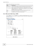
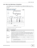
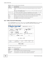
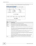
Chapter 9 VDSL Setup Table 40 VDSL Channel Profile Setup (continued) LABEL Net Data Rate MaxInterleave Delay Min INP Min INP8 PhyR SOS Min Data Rate GINP Add Cancel Clear Name Payload Rate Min INP Max Delay Applied Ports Delete Cancel DESCRIPTION Type maximum and minimum upstream/downstream transmission rates in kbps for this profile. Type the number of milliseconds of interleave delays used for downstream and upstream transmissions. It is recommended that you configure the same latency delays for both upstream and downstream. Specify the level of impulse noise (burst) protection for a slow (or interleaved) channel. Select a number between 0 and 16. This parameter is defined as the number of consecutive DMT symbols or fractions thereof. The number of symbols decides how long in one period errors can be completely corrected. A higher symbol value provides higher error correction capability, but it causes overhead and higher delay which may impact multimedia data receiving quality. Specify the level of impulse noise (burst) protection for a slow (or interleaved) channel for VDSL2 profile 30a. Enter a number between 0 and 16. The DMT symbols with a sub-carrier spacing for DS/US min INP8 is 8.625 kHz (DS/US min INP is 4.3125 kHz). Select Enable to use the VDSL physical layer for data re-transmission when impulse noise occurs. This helps to get better link connection quality. Select Disable to turn this feature off. Select Auto to have the Switch enable this feature when there is no impact to the data rate. Specify the minimum upstream/downstream data rates (guaranteed data rates) if you set the Switch to use SOS for immediate rate adjustment. The Switch drops the line if the upstream or downstream data rate goes down below the set data rate. This field displays the upstream/downstream G.INP mode. Click Modify to change the G.INP settings. Click Add to save the new settings to the Switch. It then displays in the summary table at the bottom of the screen. Click Cancel to reset the fields to your previous configuration. Click Clear to clear the fields to the factory defaults. This field displays the descriptive name of a profile. This field displays the configured maximum upstream and downstream data transmission rates in megabits per second in a profile. This field displays the configured minimum upstream and downstream impulse noise protection levels in a profile. This field displays the configured maximum upstream and downstream interleave delays in a profile. This field displays the VDSL port number(s) to which this profile is applied. Check the rule(s) that you want to remove in the Delete column and then click the Delete button. Click Cancel to clear the selected checkboxes in the Delete column. VES1724-56 User's Guide 117
-
 1
1 -
2
-
3
-
4
-
5
-
6
-
7
-
8
-
9
-
10
-
11
-
12
-
13
-
14
-
15
-
16
-
17
-
18
-
19
-
20
-
21
-
22
-
23
-
24
-
25
-
26
-
27
-
28
-
29
-
30
-
31
-
32
-
33
-
34
-
35
-
36
-
37
-
38
-
39
-
40
-
41
-
42
-
43
-
44
-
45
-
46
-
47
-
48
-
49
-
50
-
51
-
52
-
53
-
54
-
55
-
56
-
57
-
58
-
59
-
60
-
61
-
62
-
63
-
64
-
65
-
66
-
67
-
68
-
69
-
70
-
71
-
72
-
73
-
74
-
75
-
76
-
77
-
78
-
79
-
80
-
81
-
82
-
83
-
84
-
85
-
86
-
87
-
88
-
89
-
90
-
91
-
92
-
93
-
94
-
95
-
96
-
97
-
98
-
99
-
100
-
101
-
102
-
103
-
104
-
105
-
106
-
107
-
108
-
109
-
110
-
111
-
 112
112 -
 113
113 -
 114
114 -
 115
115 -
 116
116 -
 117
117 -
 118
118 -
 119
119 -
 120
120 -
 121
121 -
 122
122 -
123
-
124
-
125
-
126
-
127
-
128
-
129
-
130
-
131
-
132
-
133
-
134
-
135
-
136
-
137
-
138
-
139
-
140
-
141
-
142
-
143
-
144
-
145
-
146
-
147
-
148
-
149
-
150
-
151
-
152
-
153
-
154
-
155
-
156
-
157
-
158
-
159
-
160
-
161
-
162
-
163
-
164
-
165
-
166
-
167
-
168
-
169
-
170
-
171
-
172
-
173
-
174
-
175
-
176
-
177
-
178
-
179
-
180
-
181
-
182
-
183
-
184
-
185
-
186
-
187
-
188
-
189
-
190
-
191
-
192
-
193
-
194
-
195
-
196
-
197
-
198
-
199
-
200
-
201
-
202
-
203
-
204
-
205
-
206
-
207
-
208
-
209
-
210
-
211
-
212
-
213
-
214
-
215
-
216
-
217
-
218
-
219
-
220
-
221
-
222
-
223
-
224
-
225
-
226
-
227
-
228
-
229
-
230
-
231
-
232
-
233
-
234
-
235
-
236
-
237
-
238
-
239
-
240
-
241
-
242
-
243
-
244
-
245
-
246
-
247
-
248
-
249
-
250
-
251
-
252
-
253
-
254
-
255
-
256
-
257
-
258
-
259
-
260
-
261
-
262
-
263
-
264
-
265
-
266
-
267
-
268
-
269
-
270
-
271
-
272
-
273
-
274
-
275
-
276
-
277
-
278
-
279
-
280
-
281
-
282
-
283
-
284
-
285
-
286
-
287
-
288
-
289
-
290
-
291
-
292
-
293
-
294
-
295
-
296
-
297
-
298
-
299
-
300
-
301
-
302
-
303
-
304
-
305
-
306
-
307
-
308
-
309
-
310
-
311
-
312
-
313
-
314
-
315
-
316
-
317
-
318
-
319
-
320
-
321
-
322
-
323
-
324
-
325
-
326
-
327
-
328
-
329
-
330
-
331
-
332
-
333
-
334
-
335
-
336
-
337
-
338
-
339
-
340
-
341
-
342
-
343
-
344
-
345
-
346
-
347
-
348
-
349
-
350
-
351
-
352
-
353
-
354
-
355
-
356
-
357
-
358
-
359
-
360
-
361
-
362
-
363
-
364
-
365
-
366
-
367
-
368
-
369
-
370
-
371
-
372
-
373
-
374
-
375
-
376
-
377
-
378
-
379
-
380
-
381
-
382
-
383
-
384
-
385
-
386
-
387
-
388
-
389
-
390
-
391
-
392
-
393
-
394
-
395
-
396
-
397
-
398
-
399
-
400
-
401
-
402
-
403
-
404
-
405
-
406
-
407
-
408
-
409
-
410
-
411
-
412
-
413
-
414
 |
 |
