ZyXEL VES1724-56B2 User Guide - Page 118
VDSL G.INP Setup
 |
View all ZyXEL VES1724-56B2 manuals
Add to My Manuals
Save this manual to your list of manuals |
Page 118 highlights
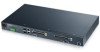
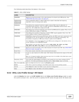
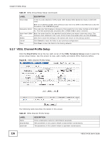
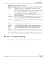
Chapter 9 VDSL Setup 9.3.8 VDSL G.INP Setup Click the Modify link in the VDSL Channel Profile Setup screen to open the screen shown below. Use this screen to modify the G.INP settings. Figure 62 VDSL Channel Profile Setup > G.INP The following table describes the labels in this screen. Table 41 VDSL Channel Profile Setup > G.INP LABEL DownStream Upstream G.INP Mode Effective Throughput Net Data Rate(NDR) Shine Ratio LEFTR Threshold Max Delay Min Delay Min INP DESCRIPTION The parameters in this column relate to downstream transmissions. The parameters in this column relate to upstream transmissions. Select G.INP retransmission mode. Forbidden: G.INP is disabled on the Switch. Preferred: G.INP is enabled if the far-end (CPE device) supports it. Forced: The VDSL connection can be established only if the far-end supports G.INP mode. Test: G.INP is enabled only in test mode. Specify the maximum and minimum value allowed for the ETR (Effective Throughput Rate). Specify the maximum downstream/upstream net data rate. Specifies the loss of data rate you predict to occur within 1 second due to SHINEs (Single high impulse noise events). The valid values are all multiples of 0.001 and between 0 and 0.1. Specify the lower rate limit (fraction of NDR). A Low Error Free Rate (LEFTR) defect is declared when the rate falls below the threshold. Specify the maximum delay (from 1 to 63 in ms) that is added to the retransmission delay caused by retransmissions. Specify the minimum delay (from 0 to 63 in ms) that is added to the retransmission delay caused by retransmissions. Specify the minimum level of impulse noise (burst) protection. 118 VES1724-56 User's Guide
-
 1
1 -
2
-
3
-
4
-
5
-
6
-
7
-
8
-
9
-
10
-
11
-
12
-
13
-
14
-
15
-
16
-
17
-
18
-
19
-
20
-
21
-
22
-
23
-
24
-
25
-
26
-
27
-
28
-
29
-
30
-
31
-
32
-
33
-
34
-
35
-
36
-
37
-
38
-
39
-
40
-
41
-
42
-
43
-
44
-
45
-
46
-
47
-
48
-
49
-
50
-
51
-
52
-
53
-
54
-
55
-
56
-
57
-
58
-
59
-
60
-
61
-
62
-
63
-
64
-
65
-
66
-
67
-
68
-
69
-
70
-
71
-
72
-
73
-
74
-
75
-
76
-
77
-
78
-
79
-
80
-
81
-
82
-
83
-
84
-
85
-
86
-
87
-
88
-
89
-
90
-
91
-
92
-
93
-
94
-
95
-
96
-
97
-
98
-
99
-
100
-
101
-
102
-
103
-
104
-
105
-
106
-
107
-
108
-
109
-
110
-
111
-
112
-
 113
113 -
 114
114 -
 115
115 -
 116
116 -
 117
117 -
 118
118 -
 119
119 -
 120
120 -
 121
121 -
 122
122 -
 123
123 -
124
-
125
-
126
-
127
-
128
-
129
-
130
-
131
-
132
-
133
-
134
-
135
-
136
-
137
-
138
-
139
-
140
-
141
-
142
-
143
-
144
-
145
-
146
-
147
-
148
-
149
-
150
-
151
-
152
-
153
-
154
-
155
-
156
-
157
-
158
-
159
-
160
-
161
-
162
-
163
-
164
-
165
-
166
-
167
-
168
-
169
-
170
-
171
-
172
-
173
-
174
-
175
-
176
-
177
-
178
-
179
-
180
-
181
-
182
-
183
-
184
-
185
-
186
-
187
-
188
-
189
-
190
-
191
-
192
-
193
-
194
-
195
-
196
-
197
-
198
-
199
-
200
-
201
-
202
-
203
-
204
-
205
-
206
-
207
-
208
-
209
-
210
-
211
-
212
-
213
-
214
-
215
-
216
-
217
-
218
-
219
-
220
-
221
-
222
-
223
-
224
-
225
-
226
-
227
-
228
-
229
-
230
-
231
-
232
-
233
-
234
-
235
-
236
-
237
-
238
-
239
-
240
-
241
-
242
-
243
-
244
-
245
-
246
-
247
-
248
-
249
-
250
-
251
-
252
-
253
-
254
-
255
-
256
-
257
-
258
-
259
-
260
-
261
-
262
-
263
-
264
-
265
-
266
-
267
-
268
-
269
-
270
-
271
-
272
-
273
-
274
-
275
-
276
-
277
-
278
-
279
-
280
-
281
-
282
-
283
-
284
-
285
-
286
-
287
-
288
-
289
-
290
-
291
-
292
-
293
-
294
-
295
-
296
-
297
-
298
-
299
-
300
-
301
-
302
-
303
-
304
-
305
-
306
-
307
-
308
-
309
-
310
-
311
-
312
-
313
-
314
-
315
-
316
-
317
-
318
-
319
-
320
-
321
-
322
-
323
-
324
-
325
-
326
-
327
-
328
-
329
-
330
-
331
-
332
-
333
-
334
-
335
-
336
-
337
-
338
-
339
-
340
-
341
-
342
-
343
-
344
-
345
-
346
-
347
-
348
-
349
-
350
-
351
-
352
-
353
-
354
-
355
-
356
-
357
-
358
-
359
-
360
-
361
-
362
-
363
-
364
-
365
-
366
-
367
-
368
-
369
-
370
-
371
-
372
-
373
-
374
-
375
-
376
-
377
-
378
-
379
-
380
-
381
-
382
-
383
-
384
-
385
-
386
-
387
-
388
-
389
-
390
-
391
-
392
-
393
-
394
-
395
-
396
-
397
-
398
-
399
-
400
-
401
-
402
-
403
-
404
-
405
-
406
-
407
-
408
-
409
-
410
-
411
-
412
-
413
-
414
 |
 |
