Asus DiGiMatrix User Guide - Page 113
Connectors
 |
View all Asus DiGiMatrix manuals
Add to My Manuals
Save this manual to your list of manuals |
Page 113 highlights
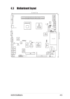
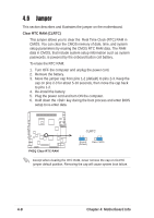
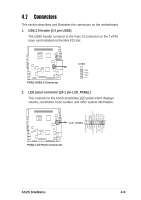
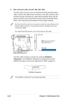
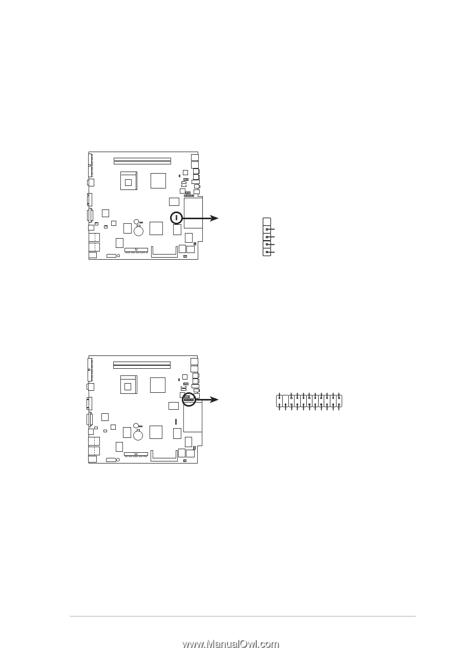
4.7 Connectors This section describes and illustrates the connectors on the motherboard. 1. USB 2.0 header (5-1 pin USB5) The USB5 header connects to the 4-pin J3 connector on the TV/FM tuner card installed on the Mini PCI slot. P4SQ P4SQ USB2.0 Connector USB5 GND USB+ USB+5V 2. LED panel connector (20-1 pin LCD_PANEL) This connects to the ASUS proprietary LED panel which displays volume, clock/timer, track number, and other system information. vol_up# SMBCK SMBDA DJ_SCANFW DJ_PLAY PIC_STB PIC_CLK PIC_CLK PIC_STB +5VSB vol_down# 12V GND +5VSB DJ_SCANRW +5V PIC_DOUT PIC_DIN PIC_DIN PIC_DOUT GND 1 LCD_PANEL P4SQ P4SQ LCD Panel Connector ASUS DiGiMatrix 4-9
-
 1
1 -
2
-
3
-
4
-
5
-
6
-
7
-
8
-
9
-
10
-
11
-
12
-
13
-
14
-
15
-
16
-
17
-
18
-
19
-
20
-
21
-
22
-
23
-
24
-
25
-
26
-
27
-
28
-
29
-
30
-
31
-
32
-
33
-
34
-
35
-
36
-
37
-
38
-
39
-
40
-
41
-
42
-
43
-
44
-
45
-
46
-
47
-
48
-
49
-
50
-
51
-
52
-
53
-
54
-
55
-
56
-
57
-
58
-
59
-
60
-
61
-
62
-
63
-
64
-
65
-
66
-
67
-
68
-
69
-
70
-
71
-
72
-
73
-
74
-
75
-
76
-
77
-
78
-
79
-
80
-
81
-
82
-
83
-
84
-
85
-
86
-
87
-
88
-
89
-
90
-
91
-
92
-
93
-
94
-
95
-
96
-
97
-
98
-
99
-
100
-
101
-
102
-
103
-
104
-
105
-
106
-
107
-
 108
108 -
 109
109 -
 110
110 -
 111
111 -
 112
112 -
 113
113 -
 114
114 -
 115
115 -
 116
116 -
 117
117 -
 118
118 -
119
-
120
-
121
-
122
-
123
-
124
-
125
-
126
-
127
-
128
-
129
-
130
-
131
-
132
-
133
-
134
-
135
-
136
-
137
-
138
-
139
-
140
-
141
-
142
-
143
-
144
-
145
-
146
-
147
-
148
-
149
-
150
-
151
-
152
-
153
-
154
-
155
-
156
-
157
-
158
 |
 |
4-9
ASUS DiGiMatrix
4.7
Connectors
This section describes and illustrates the connectors on the motherboard.
1.
USB 2.0 header (5-1 pin USB5)
The USB5 header connects to the 4-pin J3 connector on the TV/FM
tuner card installed on the Mini PCI slot.
P4SQ
P4SQ USB2.0 Connector
USB5
GND
USB+
+5V
USB-
P4SQ
P4SQ LCD Panel Connector
+5VSB
GND
PIC_DOUT
PIC_STB
PIC_CLK
PIC_DIN
PIC_DIN
PIC_CLK
PIC_STB
PIC_DOUT
+5V
DJ_PLAY
DJ_SCANFW
DJ_SCANRW
+5VSB
SMBDA
SMBCK
GND
12V
vol_up#
vol_down#
1
LCD_PANEL
2.
LED panel connector (20-1 pin LCD_PANEL)
This connects to the ASUS proprietary LED panel which displays
volume, clock/timer, track number, and other system information.