Asus DiGiMatrix User Guide - Page 16
Rear panel
 |
View all Asus DiGiMatrix manuals
Add to My Manuals
Save this manual to your list of manuals |
Page 16 highlights
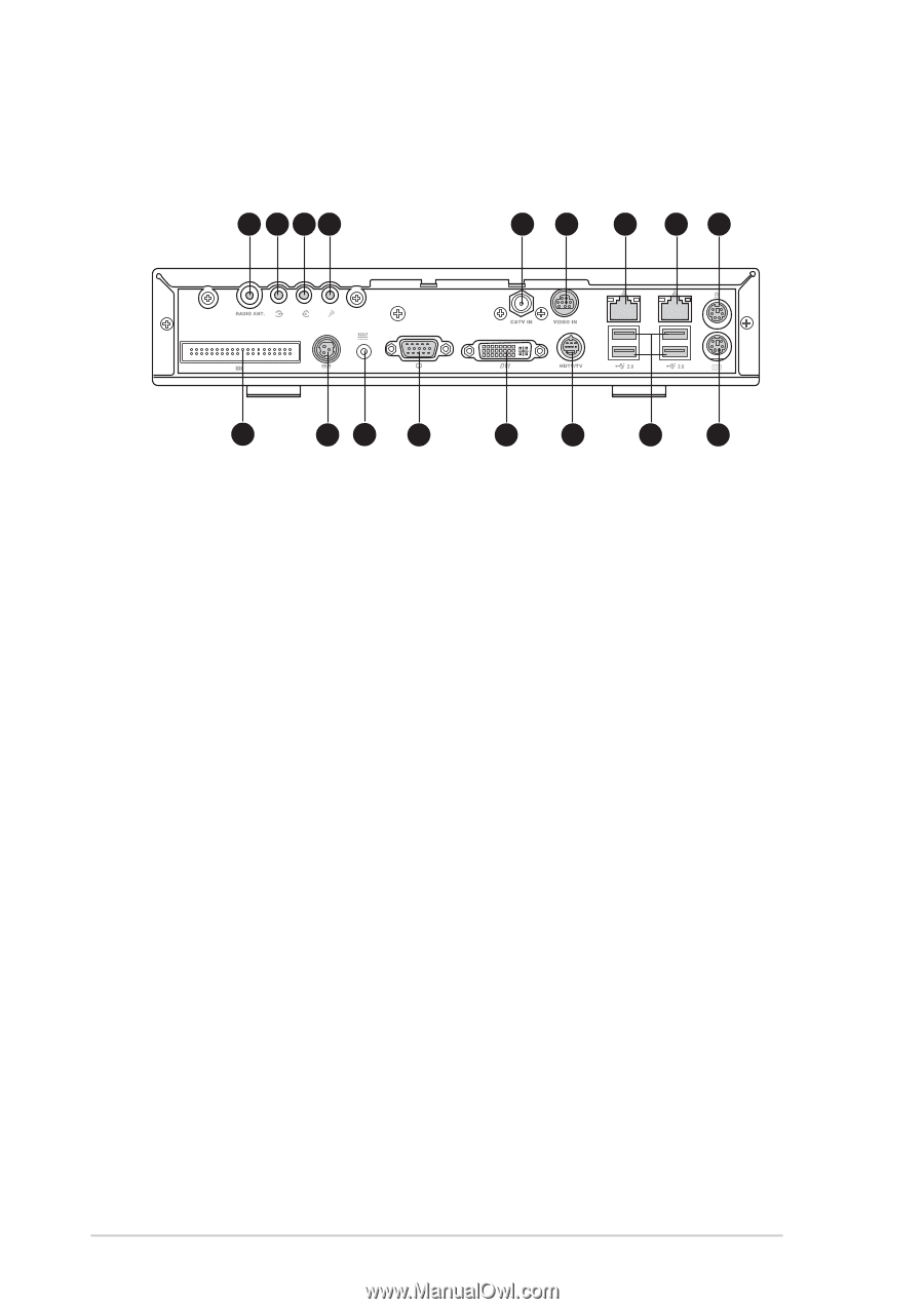
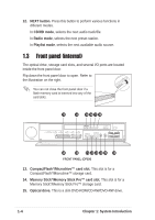
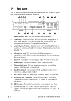
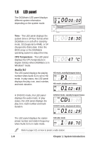
1.4 Rear panel The DiGiMatrix rear panel includes the power socket and several I/O ports that allow convenient connection of devices. 1 234 56 7 89 10 11 12 13 14 15 16 17 1. Radio antenna port. This port connects the FM antenna. 2. Line In port. This Line In (light blue) port connects a tape player or other audio sources. In 6-channel mode, the function of this port becomes Low Frequency Enhanced Output/Center. 3. Line Out port. This Line Out (lime) port connects a headphone or a speaker. In 4/6-channel mode, the function of this port becomes Front Speaker Out. 4. Microphone port. This Microphone (pink) port connects a microphone. In 4/6-channel mode, the function of this port becomes Surround Speaker. 5. Cable TV connector. This connects a cable TV twist-on connector. 6. Video In port. This port connects a video casette recorder. 7. Ethernet LAN port. This port allows connection to a Local Area Network (LAN) through a network hub. 8. Gigabit LAN port. This port allows high speed connection to the Internet via a DSL or cable modem. 9. PS/2 mouse port. This green 6-pin connector is for a PS/2 mouse. 10. Secondary IDE connector. This interface connects the optional DiGiMatrix subsystem. See page A-2 for details on the DiGiMatrix subsystem. 11. DC IN socket. This socket connects the power adapter and plug. 12. DC OUT socket. This socket connects the DC power cable that supplies power to the optional DiGiMatrix Subsystem. See page A-4 for details. 1-6 Chapter 1: System Introduction
-
 1
1 -
2
-
3
-
4
-
5
-
6
-
7
-
8
-
9
-
10
-
 11
11 -
 12
12 -
 13
13 -
 14
14 -
 15
15 -
 16
16 -
 17
17 -
 18
18 -
 19
19 -
 20
20 -
 21
21 -
22
-
23
-
24
-
25
-
26
-
27
-
28
-
29
-
30
-
31
-
32
-
33
-
34
-
35
-
36
-
37
-
38
-
39
-
40
-
41
-
42
-
43
-
44
-
45
-
46
-
47
-
48
-
49
-
50
-
51
-
52
-
53
-
54
-
55
-
56
-
57
-
58
-
59
-
60
-
61
-
62
-
63
-
64
-
65
-
66
-
67
-
68
-
69
-
70
-
71
-
72
-
73
-
74
-
75
-
76
-
77
-
78
-
79
-
80
-
81
-
82
-
83
-
84
-
85
-
86
-
87
-
88
-
89
-
90
-
91
-
92
-
93
-
94
-
95
-
96
-
97
-
98
-
99
-
100
-
101
-
102
-
103
-
104
-
105
-
106
-
107
-
108
-
109
-
110
-
111
-
112
-
113
-
114
-
115
-
116
-
117
-
118
-
119
-
120
-
121
-
122
-
123
-
124
-
125
-
126
-
127
-
128
-
129
-
130
-
131
-
132
-
133
-
134
-
135
-
136
-
137
-
138
-
139
-
140
-
141
-
142
-
143
-
144
-
145
-
146
-
147
-
148
-
149
-
150
-
151
-
152
-
153
-
154
-
155
-
156
-
157
-
158
 |
 |