Autodesk 05726-091452-9060 User Guide - Page 34
Calibration Entity Settings Colors
 |
UPC - 606121590040
View all Autodesk 05726-091452-9060 manuals
Add to My Manuals
Save this manual to your list of manuals |
Page 34 highlights
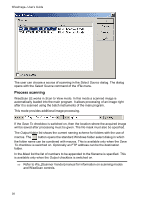
3 Basics Calibration Entity Settings Section This section enables you to change the color, drawing style, and other display parameters of a special object, used in the calibrating procedure. For each type of calibration point (real, measured, and adjusted) you can specify the following parameters: Parameter Color Show label Show grid Show arrows Purpose Changes the color of a specified point type Turns on/off the display of a calibration point name Turns on/off the calibration grid Turns on/off the display of arrows on ends of lines, connecting calibration points Show arrow line Fill arrow Show point markers Turns on/off the display of lines, connecting calibration points Shows filled arrows Turns on/off the display of calibration points markers To turn on the display of an element, click on the appropriate box. To change an object color, double-click a color pattern and select a desired color from the dialog box. Colors Section This section enables you to manage working colors and color elements of the program interface, such as selection highlighting, frame color of the preview area, etc. To change a color Double-click an appropriate item, or select item and click Modify. Select new color from the dialog. Click OK. Parameter Raster Selection Preview Frame Fill Found Raster Symbol Purpose The color of the raster selection. The color of the preview area frame. Floodfill color on color images. A color, that highlights raster objects found during the search/replace procedure. 33
-
 1
1 -
2
-
3
-
4
-
5
-
6
-
7
-
8
-
9
-
10
-
11
-
12
-
13
-
14
-
15
-
16
-
17
-
18
-
19
-
20
-
21
-
22
-
23
-
24
-
25
-
26
-
27
-
28
-
 29
29 -
 30
30 -
 31
31 -
 32
32 -
 33
33 -
 34
34 -
 35
35 -
 36
36 -
 37
37 -
 38
38 -
 39
39 -
40
-
41
-
42
-
43
-
44
-
45
-
46
-
47
-
48
-
49
-
50
-
51
-
52
-
53
-
54
-
55
-
56
-
57
-
58
-
59
-
60
-
61
-
62
-
63
-
64
-
65
-
66
-
67
-
68
-
69
-
70
-
71
-
72
-
73
-
74
-
75
-
76
-
77
-
78
-
79
-
80
-
81
-
82
-
83
-
84
-
85
-
86
-
87
-
88
-
89
-
90
-
91
-
92
-
93
-
94
-
95
-
96
-
97
-
98
-
99
-
100
-
101
-
102
-
103
-
104
-
105
-
106
-
107
-
108
-
109
-
110
-
111
-
112
-
113
-
114
-
115
-
116
-
117
-
118
-
119
-
120
-
121
-
122
-
123
-
124
-
125
-
126
-
127
-
128
-
129
-
130
-
131
-
132
-
133
-
134
-
135
-
136
-
137
-
138
-
139
-
140
-
141
-
142
-
143
-
144
-
145
-
146
-
147
-
148
-
149
-
150
-
151
-
152
-
153
-
154
-
155
-
156
-
157
-
158
-
159
-
160
-
161
-
162
-
163
-
164
-
165
-
166
-
167
-
168
-
169
-
170
-
171
-
172
-
173
-
174
-
175
-
176
-
177
-
178
-
179
-
180
-
181
-
182
-
183
-
184
-
185
-
186
-
187
-
188
-
189
-
190
-
191
-
192
-
193
-
194
-
195
-
196
-
197
-
198
-
199
-
200
-
201
-
202
-
203
-
204
-
205
-
206
-
207
-
208
-
209
-
210
-
211
-
212
-
213
-
214
-
215
-
216
-
217
-
218
-
219
-
220
-
221
-
222
-
223
-
224
-
225
-
226
-
227
-
228
-
229
-
230
-
231
-
232
-
233
-
234
-
235
 |
 |
