Campbell Scientific CSAT3B CSAT3B Three-Dimensional Sonic Anemometer - Page 21
Common Accessories - csat3
 |
View all Campbell Scientific CSAT3B manuals
Add to My Manuals
Save this manual to your list of manuals |
Page 21 highlights
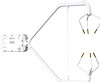
CSAT3B Three-Dimensional Sonic Anemometer 5.2.3 Common Accessories Common accessories for the CSAT3B include cables as well as other equipment to make sensible heat flux measurements. A fine-wire thermocouple is an example of an additional sensor often used with a CSAT3B. Descriptions of cables and other common accessories are described in greater detail in the following sections. 5.2.3.1 Power and Communications Cables Cables required for the CSAT3B to be functional, must be ordered along with the CSAT3B. The types of cables needed for a specific communications mode, are outlined below. NOTE Unlike the earlier CSAT3, default-length cables are not included. This allows the user to specify the exact length, communication type, and connector type of the cable(s) needed for the application. Campbell Scientific uses a system for naming cables that provide specific information about details of the cable and some information about the use of the cable. • The '-L' in the cable model name is an option that denotes a userspecified length of cable in feet. • The '-PT' is a cable option that specifies one end of the cable to have pigtail wires for wiring to a power source, datalogger terminals, or a wiring bus. The other end has an M16 connector for connecting to the corresponding port at the back of the CSAT3B block. • The '-MC' option designates an M16 connector on both ends of the cable and is used to daisy-chain several CSAT3B instruments together in series. NOTE Daisy-chaining requires ordering the 30293 splitter (see Section 5.2.4.1, Power/SDM Splitter, and Section 5.2.4.2, CPI/RS-485 Splitter) for each CSAT3B in series, except the terminal one. • The '-RJ' option has an RJ-45 connector on one end for connecting directly to the CPI port on a datalogger such as the CR6 or to a CPI port on the HUB-CPI if a network of several CPI devices are being installed in a star topology. The other end of the cable has an M16 connector for connecting to the CSAT3B block. The types of cables needed for a specific communications mode are outlined below. For information on maximum cable lengths, refer to the communications specifications in Section 6.2, Communications. Power/SDM Cable (CSAT3BCBL1) To use SDM communications to collect data from a CSAT3B with a datalogger, the CSAT3BCBL1-L-PT or CSAT3BCBL1-L-MC should be ordered. The two versions are shown in FIGURE 5-3. This cable is used to transmit both power and SDM communication signals. 11
-
 1
1 -
2
-
3
-
4
-
5
-
6
-
7
-
8
-
9
-
10
-
11
-
12
-
13
-
14
-
15
-
 16
16 -
 17
17 -
 18
18 -
 19
19 -
 20
20 -
 21
21 -
 22
22 -
 23
23 -
 24
24 -
 25
25 -
 26
26 -
27
-
28
-
29
-
30
-
31
-
32
-
33
-
34
-
35
-
36
-
37
-
38
-
39
-
40
-
41
-
42
-
43
-
44
-
45
-
46
-
47
-
48
-
49
-
50
-
51
-
52
-
53
-
54
-
55
-
56
-
57
-
58
-
59
-
60
-
61
-
62
-
63
-
64
-
65
-
66
-
67
-
68
-
69
-
70
-
71
-
72
-
73
-
74
-
75
-
76
-
77
-
78
-
79
-
80
-
81
-
82
-
83
-
84
-
85
-
86
-
87
-
88
 |
 |
