Campbell Scientific CSAT3B CSAT3B Three-Dimensional Sonic Anemometer - Page 31
Installation
 |
View all Campbell Scientific CSAT3B manuals
Add to My Manuals
Save this manual to your list of manuals |
Page 31 highlights
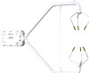
CSAT3B Three-Dimensional Sonic Anemometer FIGURE 6-1. Dimensions of CSAT3B 7. Installation Campbell Scientific recommends that the CSAT3B and data acquisition system is setup in a laboratory setting before field installation. This provides an opportunity to verify that settings and programs are correct in a controlled environment. Prior to setup, the user needs to know information about the desired sensor settings, orienting, mounting, and leveling the CSAT3B, which is covered in the following sections. 7.1 Settings Prior to installation, the CSAT3B's settings should be verified. This is done by the following steps: 1. Provide power to the CSAT3B by connecting the M16 connector of either a CSAT3BCBL1 or CSAT3BCBL2 to the Power/SDM port on the back of the CSAT3B block. The other end of this cable will have red and black wire leads that should be connected to a 9.5 to 32 Vdc power source. (In the case of the CSAT3BCBL1, the other wire leads need not be connected.) 21
-
 1
1 -
2
-
3
-
4
-
5
-
6
-
7
-
8
-
9
-
10
-
11
-
12
-
13
-
14
-
15
-
16
-
17
-
18
-
19
-
20
-
21
-
22
-
23
-
24
-
25
-
 26
26 -
 27
27 -
 28
28 -
 29
29 -
 30
30 -
 31
31 -
 32
32 -
 33
33 -
 34
34 -
 35
35 -
 36
36 -
37
-
38
-
39
-
40
-
41
-
42
-
43
-
44
-
45
-
46
-
47
-
48
-
49
-
50
-
51
-
52
-
53
-
54
-
55
-
56
-
57
-
58
-
59
-
60
-
61
-
62
-
63
-
64
-
65
-
66
-
67
-
68
-
69
-
70
-
71
-
72
-
73
-
74
-
75
-
76
-
77
-
78
-
79
-
80
-
81
-
82
-
83
-
84
-
85
-
86
-
87
-
88
 |
 |
