Campbell Scientific CSAT3B CSAT3B Three-Dimensional Sonic Anemometer - Page 42
SDM Communications
 |
View all Campbell Scientific CSAT3B manuals
Add to My Manuals
Save this manual to your list of manuals |
Page 42 highlights
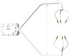
CSAT3B Three-Dimensional Sonic Anemometer NOTE For all communications types, if the total number of CSAT3Bs and other sensors powered by the datalogger exceeds the limit of output current from the datalogger, the power wires must be connected to a separate 12 to 32 Vdc power supply. For long cables, a higher voltage power supply is recommended as there will be voltage loss over long distances. WARNING Not all of the dataloggers that are compatible with the CSAT3B support the same voltage input range as the CSAT3B. While the CSAT3B supports voltage of up to 32 Vdc, many dataloggers require lower voltage. For example, the CR800, CR1000, and CR3000 require 9.6 to 16 Vdc when connecting to the front panel voltage input. If a CR3000 has a rechargeable base, then a 17 to 28 Vdc power supply may be connected to the base. Unlike most of the dataloggers, the CR6 does support up to 32 Vdc if the power supply is connected to the CHG input terminals. For more details, refer to a datalogger user manual. 7.7.1 SDM Communications If data collection from the anemometer is to be accomplished using a datalogger with SDM communications, connect a CSAT3BCBL1 to the Power/SDM port by screwing in the M16 connector into the port until tight as shown in FIGURE 7-8. No other cables are required for SDM communications, as the CSAT3BCBL1 contains both power and SDM wiring. If only one CSAT3B is being measured, the opposite end of the cable will have wire pigtails if connecting directly to the ports on a datalogger. Refer to Section 4.2, Communications Connections, for this wiring. Connect the white, yellow, and blue wires to the SDM-C1, SDM-C2, and SDM-C3 ports respectively, on a datalogger (FIGURE 7-9). On a datalogger or to another 9.5 to 32 Vdc power supply, connect the red and black wires to the 12 V and G ports, respectively. See FIGURE 7-9 and TABLE 7-3 for wiring and wire color designations. For applications requiring very long cable lengths, a higher voltage power supply is recommended as voltage drop over long distances will occur and the CSAT3B requires a minimum of 9.5 Vdc. 32
-
 1
1 -
2
-
3
-
4
-
5
-
6
-
7
-
8
-
9
-
10
-
11
-
12
-
13
-
14
-
15
-
16
-
17
-
18
-
19
-
20
-
21
-
22
-
23
-
24
-
25
-
26
-
27
-
28
-
29
-
30
-
31
-
32
-
33
-
34
-
35
-
36
-
 37
37 -
 38
38 -
 39
39 -
 40
40 -
 41
41 -
 42
42 -
 43
43 -
 44
44 -
 45
45 -
 46
46 -
 47
47 -
48
-
49
-
50
-
51
-
52
-
53
-
54
-
55
-
56
-
57
-
58
-
59
-
60
-
61
-
62
-
63
-
64
-
65
-
66
-
67
-
68
-
69
-
70
-
71
-
72
-
73
-
74
-
75
-
76
-
77
-
78
-
79
-
80
-
81
-
82
-
83
-
84
-
85
-
86
-
87
-
88
 |
 |
