Campbell Scientific CSAT3B CSAT3B Three-Dimensional Sonic Anemometer - Page 48
Refer
 |
View all Campbell Scientific CSAT3B manuals
Add to My Manuals
Save this manual to your list of manuals |
Page 48 highlights
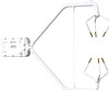
CSAT3B Three-Dimensional Sonic Anemometer NOTE CPI Daisy-chain Topology For an application that requires CPI communication from multiple CSAT3Bs in series, or with a daisy-chain topology, first connect to each CSAT3B as described in Section 7.1, Settings, to give each sensor a unique CPI address. Then connect a CSAT3BCBL2 to the Power/SDM port and a CSAT3BCBL3 to the CPI/RS-485 port on the terminal CSAT3B. The opposite end of the power cable should use an M16 connector to mate with one of the split M16 connectors on the power/SDM splitter (pn 30293). The opposite end of the CPI cable should use an M16 connector to mate with one of the split M16 connectors on the CPI/RS-485 splitter (pn 30294). Screw the side of the splitters with only one M16 connector to the Power/SDM and CPI/RS-485 ports of the second CSAT3B. Connect another set of cables from these splitters down to the next CSAT3B. Continue the daisy-chain until the last CSAT3B, where a final CSAT3BCBL2 should have pigtail wire ends to connect to the 12 V and G ports of a datalogger or to a 12 to 32 Vdc power supply. The final CSAT3BCBL3 should have an RJ-45 connector that plugs into the CPI port of the datalogger. Refer to FIGURE 7-14 for the described connections. CPI Star Topology If several CSAT3Bs using CPI communications are being connected in parallel or with a star topology, connect a CSAT3BCBL2 cable to each Power/SDM port of each CSAT3B, and connect the other wire leads to the 12 V and G ports of a datalogger or to another 12 to 32 Vdc power supply (for convenience, it's possible to use a wiring bus such as the HUB-SDM8 to bring several power wires together and then extend a single cable such as the CABLEPCBL-L from the bus to the power supply). Connect a CSAT3BCBL3 to each CPI/RS-485 port of each CSAT3B, and connect the opposite end, which should have RJ-45 connectors to a HUB-CPI. Then, use a CAT5e or CAT6 Ethernet cable to connect the HUB-CPI to the CPI port of a datalogger. Refer to FIGURE 7-15 for these connections. The sockets or ports on the HUB-CPI are all the same. It does not matter which socket is used to connect to the datalogger or to other CSAT3Bs. 38
-
 1
1 -
2
-
3
-
4
-
5
-
6
-
7
-
8
-
9
-
10
-
11
-
12
-
13
-
14
-
15
-
16
-
17
-
18
-
19
-
20
-
21
-
22
-
23
-
24
-
25
-
26
-
27
-
28
-
29
-
30
-
31
-
32
-
33
-
34
-
35
-
36
-
37
-
38
-
39
-
40
-
41
-
42
-
 43
43 -
 44
44 -
 45
45 -
 46
46 -
 47
47 -
 48
48 -
 49
49 -
 50
50 -
 51
51 -
 52
52 -
 53
53 -
54
-
55
-
56
-
57
-
58
-
59
-
60
-
61
-
62
-
63
-
64
-
65
-
66
-
67
-
68
-
69
-
70
-
71
-
72
-
73
-
74
-
75
-
76
-
77
-
78
-
79
-
80
-
81
-
82
-
83
-
84
-
85
-
86
-
87
-
88
 |
 |
