Campbell Scientific CSAT3B CSAT3B Three-Dimensional Sonic Anemometer - Page 65
Maintenance and Troubleshooting
 |
View all Campbell Scientific CSAT3B manuals
Add to My Manuals
Save this manual to your list of manuals |
Page 65 highlights
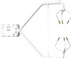
CSAT3B Three-Dimensional Sonic Anemometer 9. Maintenance and Troubleshooting 9.1 General Maintenance With no moving parts, maintenance of the CSAT3B is minimal and limited to the following: • Replacing rain wicks • Replacing the desiccant canister • Monitoring diagnostics and measurement offsets to determine when factory recalibration is needed The sections below address these maintenance activities. CAUTION The cover plate to the electronics should only be removed by qualified technicians at the factory. When covered, the electronics are well protected against transient voltages during handling and operation. Once uncovered, however, they are highly sensitive to electrostatic discharge. There are no user-serviceable components beneath the cover plate. Opening this will void the warranty on the anemometer. 9.2 Sonic Wicks Like other ultrasonic anemometers, the CSAT3B is unable to measure wind when water droplets completely obscure the face of the transducers. CSAT3B algorithm Version 5 along with sonic wicks (shown in FIGURE 9-1), improve the performance of the CSAT3B in rainy conditions. Under certain conditions, the wicking properties of the sonic wicks may not be adequate. In these circumstances, the CSAT3B may report diagnostic error conditions or erroneous data until the water droplets evaporate or are manually removed. Droplets can be removed by dabbing a cotton swab or tissue on the face of the transducer. If site conditions are such that the wicks are unnecessary, gently remove the wicks from the transducers, taking care not to damage or peel the matching layer (rubber tips) from the brass housing of the transducers. Remove the wicks during the winter, as the wicks will accumulate snow or freezing rain to the point where the transducer face will be obscured. CAUTION Lightly dab the face of the transducers to remove water droplets. Applying excessive force on the face of the transducer may damage the matching layer. Do not attempt to remove ice or frost without melting it first by gently warming the anemometer. If the wicks are to be permanently installed at the site, ensure that the wicks are located in the proper position. FIGURE 9-1 shows the proper orientation of the transducer wicks. The top wick must be flush with the transducer face, with the wick tail located at the lowest point of the transducer (FIGURE 9-1, left). The end of the bottom transducer wick must extend above the transducer 55
-
 1
1 -
2
-
3
-
4
-
5
-
6
-
7
-
8
-
9
-
10
-
11
-
12
-
13
-
14
-
15
-
16
-
17
-
18
-
19
-
20
-
21
-
22
-
23
-
24
-
25
-
26
-
27
-
28
-
29
-
30
-
31
-
32
-
33
-
34
-
35
-
36
-
37
-
38
-
39
-
40
-
41
-
42
-
43
-
44
-
45
-
46
-
47
-
48
-
49
-
50
-
51
-
52
-
53
-
54
-
55
-
56
-
57
-
58
-
59
-
 60
60 -
 61
61 -
 62
62 -
 63
63 -
 64
64 -
 65
65 -
 66
66 -
 67
67 -
 68
68 -
 69
69 -
 70
70 -
71
-
72
-
73
-
74
-
75
-
76
-
77
-
78
-
79
-
80
-
81
-
82
-
83
-
84
-
85
-
86
-
87
-
88
 |
 |
