Dell Dimension 4500C Dell Dimension 4500C Owner's Manual - Page 91
Insert the module into the connector until the module snaps into
 |
View all Dell Dimension 4500C manuals
Add to My Manuals
Save this manual to your list of manuals |
Page 91 highlights
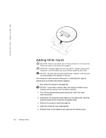
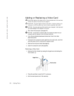
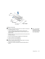
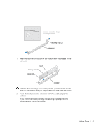
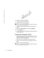
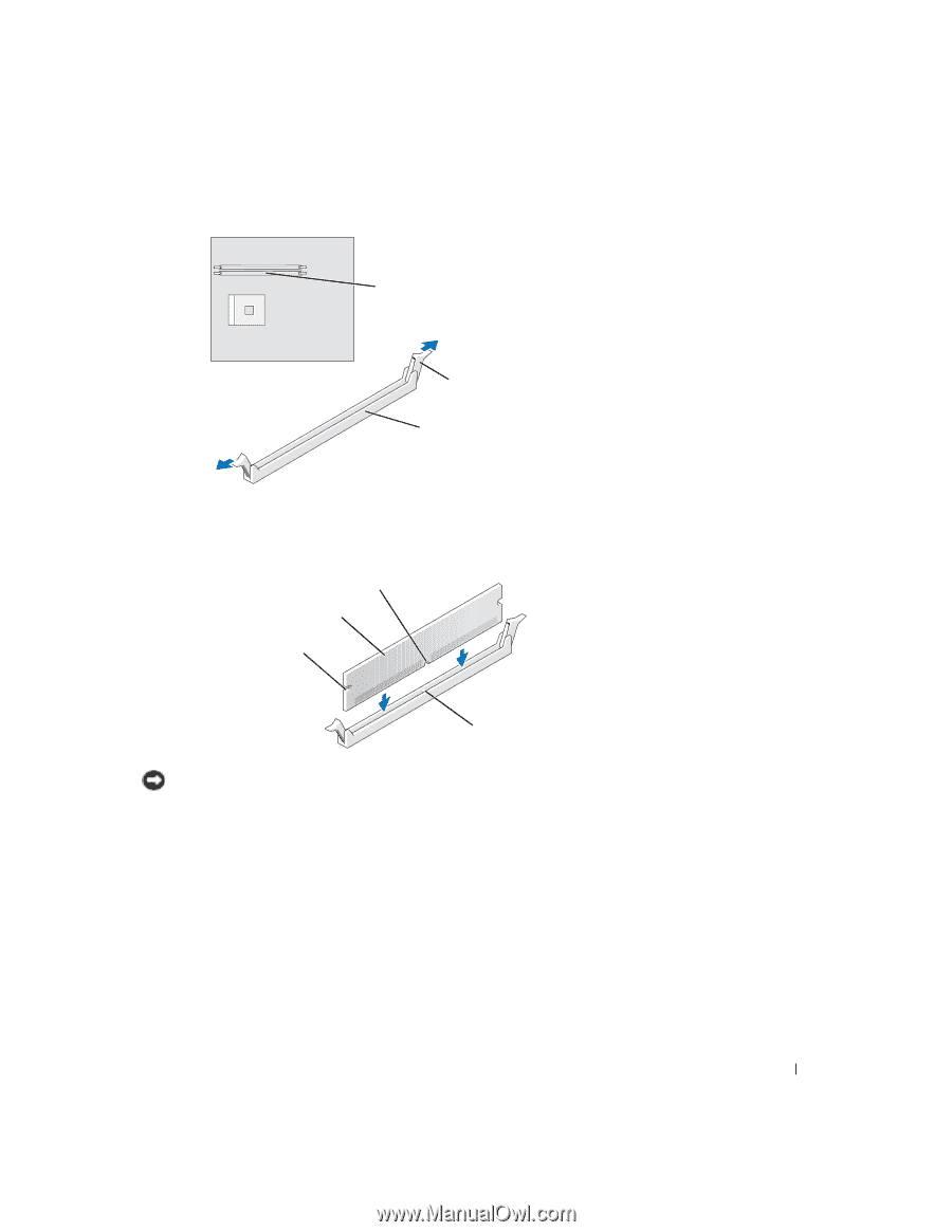
memory connector closest to microprocessor securing clips (2) connector 9 Align the notch on the bottom of the module with the crossbar in the connector. notch memory module cutouts (2) crossbar NOTICE: To avoid damage to the memory module, press the module straight down into the connector while you apply equal force to each end of the module. 10 Insert the module into the connector until the module snaps into position. If you insert the module correctly, the securing clips snap into the cutouts at each end of the module. Adding Pa rts 91
-
 1
1 -
2
-
3
-
4
-
5
-
6
-
7
-
8
-
9
-
10
-
11
-
12
-
13
-
14
-
15
-
16
-
17
-
18
-
19
-
20
-
21
-
22
-
23
-
24
-
25
-
26
-
27
-
28
-
29
-
30
-
31
-
32
-
33
-
34
-
35
-
36
-
37
-
38
-
39
-
40
-
41
-
42
-
43
-
44
-
45
-
46
-
47
-
48
-
49
-
50
-
51
-
52
-
53
-
54
-
55
-
56
-
57
-
58
-
59
-
60
-
61
-
62
-
63
-
64
-
65
-
66
-
67
-
68
-
69
-
70
-
71
-
72
-
73
-
74
-
75
-
76
-
77
-
78
-
79
-
80
-
81
-
82
-
83
-
84
-
85
-
 86
86 -
 87
87 -
 88
88 -
 89
89 -
 90
90 -
 91
91 -
 92
92 -
 93
93 -
 94
94 -
 95
95 -
 96
96 -
97
-
98
-
99
-
100
-
101
-
102
-
103
-
104
-
105
-
106
-
107
-
108
-
109
-
110
 |
 |
Adding Parts
91
9
Align the notch on the bottom of the module with the crossbar in the
connector.
NOTICE:
To avoid damage to the memory module, press the module straight
down into the connector while you apply equal force to each end of the module.
10
Insert the module into the connector until the module snaps into
position.
If you insert the module correctly, the securing clips snap into the
cutouts at each end of the module.
securing clips (2)
connector
memory connector closest
to microprocessor
notch
memory module
cutouts (2)
crossbar