Dell Latitude XFR D630 Service Manual - Page 105
Installing the Bottom Chassis, Removing the Modem Cable, Installing the Modem Cable
 |
View all Dell Latitude XFR D630 manuals
Add to My Manuals
Save this manual to your list of manuals |
Page 105 highlights
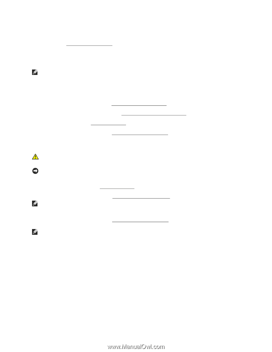
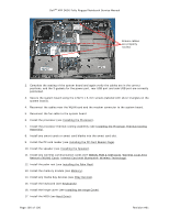
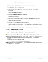
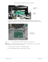
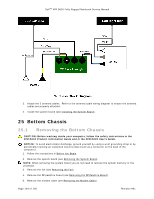
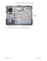
DellTM XFR D630 Fully Rugged Notebook Service Manual 6. If your XFR D630 is equipped with the optional Touch Screen, remove the stylus, tether and clip (see Stylus, Tether and Clip). 301H 25.2 Installing the Bottom Chassis NOTE: The replacement assembly will include the handle, all side and rear doors and all bottom doors except the HDD and battery doors. 1. Update the handle hardware. Install the stylus, tether and clip if previously removed. Install the shoulder strap anchors if previously removed. 2. Replace the modem cable (see Installing the Modem Cable). 302H 3. Replace the RF passthru board (see Installing the RF Passthru Board). 30H 4. Replace the fan (see Installing the Fan). 304H 5. Replace the system board (see Installing the System Board). 305H 25.3 Removing the Modem Cable CAUTION: Before working inside your computer, follow the safety instructions in the XFR D630 Product Information Guide and in the XFR D630 User's Guide. NOTICE: To avoid electrostatic discharge, ground yourself by using a wrist grounding strap or by periodically touching an unpainted metal surface (such as a connector on the back of the computer). 1. Follow the instructions in Before You Begin. 306H 2. Remove the system board (see Removing the System Board). 307H NOTE: When removing the system board you do not need to remove the system memory or the processor. 3. Remove the modem cable (see Removing the Modem Cable). 308H NOTE: When removing the modem cable, remove the tape used to attach the modem cable to the base as it will be reused for the new cable. 25.4 Installing the Modem Cable 1. Install the new modem cable. Refer to the figure below to see the proper cable routing and where to secure the cable to the base using the tape saved when removing the modem cable. Page 105 of 106 Revision A01
-
 1
1 -
2
-
3
-
4
-
5
-
6
-
7
-
8
-
9
-
10
-
11
-
12
-
13
-
14
-
15
-
16
-
17
-
18
-
19
-
20
-
21
-
22
-
23
-
24
-
25
-
26
-
27
-
28
-
29
-
30
-
31
-
32
-
33
-
34
-
35
-
36
-
37
-
38
-
39
-
40
-
41
-
42
-
43
-
44
-
45
-
46
-
47
-
48
-
49
-
50
-
51
-
52
-
53
-
54
-
55
-
56
-
57
-
58
-
59
-
60
-
61
-
62
-
63
-
64
-
65
-
66
-
67
-
68
-
69
-
70
-
71
-
72
-
73
-
74
-
75
-
76
-
77
-
78
-
79
-
80
-
81
-
82
-
83
-
84
-
85
-
86
-
87
-
88
-
89
-
90
-
91
-
92
-
93
-
94
-
95
-
96
-
97
-
98
-
99
-
 100
100 -
 101
101 -
 102
102 -
 103
103 -
 104
104 -
 105
105 -
 106
106
 |
 |