Dell Latitude XFR D630 Service Manual - Page 85
Processor Thermal-Cooling Assembly
 |
View all Dell Latitude XFR D630 manuals
Add to My Manuals
Save this manual to your list of manuals |
Page 85 highlights
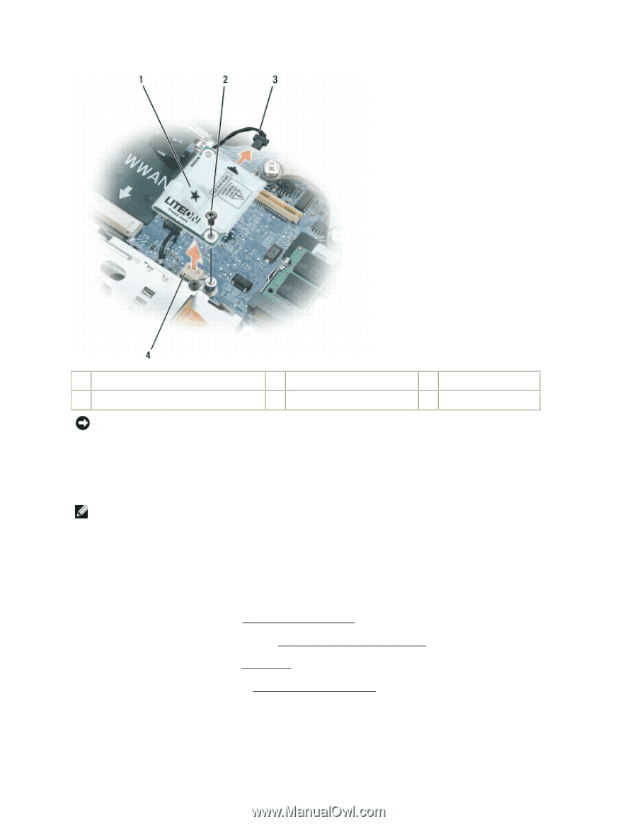
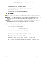
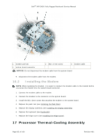
DellTM XFR D630 Fully Rugged Notebook Service Manual 1 modem pull-tab 4 system board connector 2 M2 x 3-mm screw 3 modem cable NOTICE: Do not disconnect the modem cable from the system board. 9. Disconnect the modem cable from the modem. 16.2 Installing the Modem NOTE: When replacing the modem, it is easier to connect the modem cable to the modem before you press the modem into the system board connector. 1. Connect the modem cable to the modem. 2. Connect the modem to the connector on the system board. 3. Install the M2 x 3mm screw that attaches the modem to the system board. 4. Replace the palm rest (see Installing the Palm Rest). 193H 5. Replace the display assembly (see Installing the Display Assembly). 194H 6. Replace the keyboard (see Keyboards). 195H 7. Replace the hinge cover (see Installing the Hinge Cover). 196H 17 Processor Thermal-Cooling Assembly Page 85 of 106 Revision A01
-
 1
1 -
2
-
3
-
4
-
5
-
6
-
7
-
8
-
9
-
10
-
11
-
12
-
13
-
14
-
15
-
16
-
17
-
18
-
19
-
20
-
21
-
22
-
23
-
24
-
25
-
26
-
27
-
28
-
29
-
30
-
31
-
32
-
33
-
34
-
35
-
36
-
37
-
38
-
39
-
40
-
41
-
42
-
43
-
44
-
45
-
46
-
47
-
48
-
49
-
50
-
51
-
52
-
53
-
54
-
55
-
56
-
57
-
58
-
59
-
60
-
61
-
62
-
63
-
64
-
65
-
66
-
67
-
68
-
69
-
70
-
71
-
72
-
73
-
74
-
75
-
76
-
77
-
78
-
79
-
 80
80 -
 81
81 -
 82
82 -
 83
83 -
 84
84 -
 85
85 -
 86
86 -
 87
87 -
 88
88 -
 89
89 -
 90
90 -
91
-
92
-
93
-
94
-
95
-
96
-
97
-
98
-
99
-
100
-
101
-
102
-
103
-
104
-
105
-
106
 |
 |