Dell Latitude XFR D630 Service Manual - Page 97
Removing the VGA Door
 |
View all Dell Latitude XFR D630 manuals
Add to My Manuals
Save this manual to your list of manuals |
Page 97 highlights
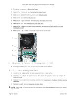
DellTM XFR D630 Fully Rugged Notebook Service Manual System Board Screw Locations 17. Remove the VGA Door from the rear panel of the notebook (see Removing the VGA Door). 27H 18. Remove the four 5-mm hex screws on the back of the computer. 19. To remove the system board: a. Lift the lower corner near the speaker. b. Grasp the system board next to the I/O dash board and lift up until the USB connectors and the gasket on the right side clear the base. c. While keeping the system board raised on the right side, push on the VGA connector to clear the base. Pull the system board towards the front and right to clear the audio ports and Wi-Fi switch on the left side, and lift out of the base. Page 97 of 106 Revision A01
-
 1
1 -
2
-
3
-
4
-
5
-
6
-
7
-
8
-
9
-
10
-
11
-
12
-
13
-
14
-
15
-
16
-
17
-
18
-
19
-
20
-
21
-
22
-
23
-
24
-
25
-
26
-
27
-
28
-
29
-
30
-
31
-
32
-
33
-
34
-
35
-
36
-
37
-
38
-
39
-
40
-
41
-
42
-
43
-
44
-
45
-
46
-
47
-
48
-
49
-
50
-
51
-
52
-
53
-
54
-
55
-
56
-
57
-
58
-
59
-
60
-
61
-
62
-
63
-
64
-
65
-
66
-
67
-
68
-
69
-
70
-
71
-
72
-
73
-
74
-
75
-
76
-
77
-
78
-
79
-
80
-
81
-
82
-
83
-
84
-
85
-
86
-
87
-
88
-
89
-
90
-
91
-
 92
92 -
 93
93 -
 94
94 -
 95
95 -
 96
96 -
 97
97 -
 98
98 -
 99
99 -
 100
100 -
 101
101 -
 102
102 -
103
-
104
-
105
-
106
 |
 |
Dell
TM
XFR D630 Fully Rugged Notebook Service Manual
Page 97 of 106
Revision A01
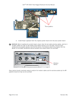
17.
Remove the VGA Door from the rear panel of the notebook (see
Removing the VGA Door
).
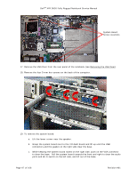
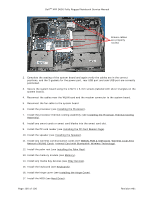
18.
Remove the four 5-mm hex screws on the back of the computer.
19.
To remove the system board:
a.
Lift the lower corner near the speaker.
b.
Grasp the system board next to the I/O dash board and lift up until the USB
connectors and the gasket on the right side clear the base.
c.
While keeping the system board raised on the right side, push on the VGA connector
to clear the base. Pull the system board towards the front and right to clear the audio
ports and Wi-Fi switch on the left side, and lift out of the base.
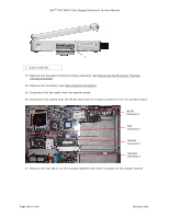
System Board
Screw Locations