Dell Latitude XFR D630 Service Manual - Page 91
Removing the PC Card Cage
 |
View all Dell Latitude XFR D630 manuals
Add to My Manuals
Save this manual to your list of manuals |
Page 91 highlights
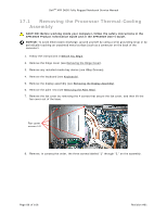
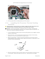
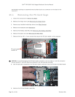
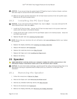
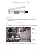
DellTM XFR D630 Fully Rugged Notebook Service Manual periodically touching an unpainted metal surface (such as a connector on the back of the computer). 19.1 Removing the PC Card Cage 1. Follow the instructions in Before You Begin. 24H 2. Remove the hinge cover (see Removing the Hinge Cover). 25H 3. Remove any installed media bay device (see XBay Devices). 26H 4. Remove the keyboard (see Keyboards). 27H 5. Remove the display assembly (see Removing the Display Assembly). 28H 6. Remove the palm rest (see Removing the Palm Rest). 29H 7. Remove the four M2 x 3-mm screws that secure the PC Card reader to the computer. PC card reader screws (4) NOTICE: To avoid damaging the PC Card reader connector, do not rotate or rock the connector as you remove it. Use firm and even pressure to lift the pull-tab vertically. 8. Use the pull-tab to disconnect the PC Card reader connector from the PC Card interface board. 9. Remove the PC Card Reader assembly. Page 91 of 106 Revision A01
-
 1
1 -
2
-
3
-
4
-
5
-
6
-
7
-
8
-
9
-
10
-
11
-
12
-
13
-
14
-
15
-
16
-
17
-
18
-
19
-
20
-
21
-
22
-
23
-
24
-
25
-
26
-
27
-
28
-
29
-
30
-
31
-
32
-
33
-
34
-
35
-
36
-
37
-
38
-
39
-
40
-
41
-
42
-
43
-
44
-
45
-
46
-
47
-
48
-
49
-
50
-
51
-
52
-
53
-
54
-
55
-
56
-
57
-
58
-
59
-
60
-
61
-
62
-
63
-
64
-
65
-
66
-
67
-
68
-
69
-
70
-
71
-
72
-
73
-
74
-
75
-
76
-
77
-
78
-
79
-
80
-
81
-
82
-
83
-
84
-
85
-
 86
86 -
 87
87 -
 88
88 -
 89
89 -
 90
90 -
 91
91 -
 92
92 -
 93
93 -
 94
94 -
 95
95 -
 96
96 -
97
-
98
-
99
-
100
-
101
-
102
-
103
-
104
-
105
-
106
 |
 |