Dell Latitude XFR D630 Service Manual - Page 56
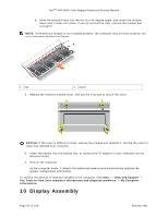
Removing the Display Assembly
 |
View all Dell Latitude XFR D630 manuals
Add to My Manuals
Save this manual to your list of manuals |
Page 56 highlights
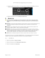
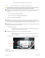
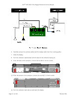
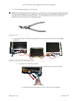
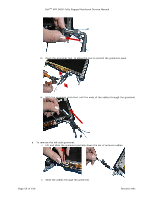
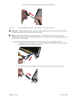
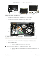
DellTM XFR D630 Fully Rugged Notebook Service Manual 10.1 Removing the Display Assembly CAUTION: Before working inside your computer, follow the safety instructions in the XFR D630 Product Information Guide and in the XFR D630 User's Guide. NOTICE: To avoid electrostatic discharge, ground yourself by using a wrist grounding strap or by periodically touching an unpainted metal surface (such as a connector on the back of the computer). 1. Follow the instructions in Before You Begin. 1H 2. Remove the hinge cover (see Removing the Hinge Cover). 12H 3. Remove the keyboard (see Keyboards). 13H NOTICE: To avoid damage to your computer, carefully reroute the cables in the appropriate cable channels when replacing the display. Route the gray and black antenna cables beneath the white antenna cable, and the black display cable on top of the white antenna cable. NOTICE: For the optional Touch Screen Display, remove the touch controller cable from the I/O board on the right side, near the right hinge. 4. Unplug the display cable: a. Pull straight up on the pull-tab that is attached to the display-feed flex cable to disconnect the cable from the system board. NOTE: The following step is only for the optional Touch Screen display. b. Disconnect the touch controller cable from the motherboard controller cable, above the heat sink. 5. Disconnect the antenna cables from their card(s) (see WLAN Card and RF Passthru Board). 14H 15H 3 2 4 1 1 WLAN card 4 Display cable connector 2 antenna cable connectors 3 RF Passthru cable connector Page 56 of 106 Revision A01
-
 1
1 -
2
-
3
-
4
-
5
-
6
-
7
-
8
-
9
-
10
-
11
-
12
-
13
-
14
-
15
-
16
-
17
-
18
-
19
-
20
-
21
-
22
-
23
-
24
-
25
-
26
-
27
-
28
-
29
-
30
-
31
-
32
-
33
-
34
-
35
-
36
-
37
-
38
-
39
-
40
-
41
-
42
-
43
-
44
-
45
-
46
-
47
-
48
-
49
-
50
-
 51
51 -
 52
52 -
 53
53 -
 54
54 -
 55
55 -
 56
56 -
 57
57 -
 58
58 -
 59
59 -
 60
60 -
 61
61 -
62
-
63
-
64
-
65
-
66
-
67
-
68
-
69
-
70
-
71
-
72
-
73
-
74
-
75
-
76
-
77
-
78
-
79
-
80
-
81
-
82
-
83
-
84
-
85
-
86
-
87
-
88
-
89
-
90
-
91
-
92
-
93
-
94
-
95
-
96
-
97
-
98
-
99
-
100
-
101
-
102
-
103
-
104
-
105
-
106
 |
 |