Dell Latitude XFR D630 Service Manual - Page 88
Processor
 |
View all Dell Latitude XFR D630 manuals
Add to My Manuals
Save this manual to your list of manuals |
Page 88 highlights
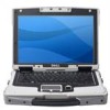
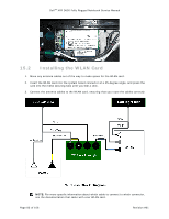
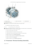
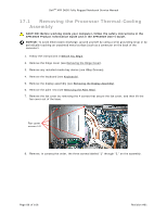
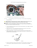
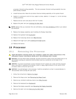
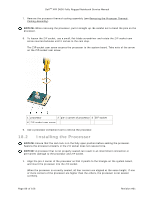
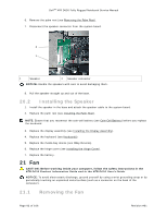
DellTM XFR D630 Fully Rugged Notebook Service Manual processor thermal-cooling assembly. The new processor thermal-cooling assembly has new pads already installed. 5. Install the heat sink. Place the processor thermal-cooling assembly on the system board. 6. Tighten in consecutive order the four captive screws, labeled "1" through "4," on the thermalcooling assembly. 7. Replace the fan cover and secure with the 4 screws. 8. Replace the palm rest (see Installing the Palm Rest). 203H NOTE: Ensure that you reconnect the coin-cell battery (see Coin-Cell Battery) before you replace 204H the keyboard. 9. Replace the display assembly (see Installing the Display Assembly). 205H 10. Replace the keyboard (see Keyboards). 206H 11. Replace the media bay device (see XBay Devices). 207H 12. Replace the hinge cover (see Installing the Hinge Cover). 208H 13. Replace the battery. 18 Processor 18.1 Removing the Processor CAUTION: Before working inside your computer, follow the safety instructions in the XFR D630 Product Information Guide and in the XFR D630 User's Guide. NOTICE: To avoid electrostatic discharge, ground yourself by using a wrist grounding strap or by periodically touching an unpainted metal surface (such as a connector on the back of the computer). NOTICE: To prevent intermittent contact between the ZIF-socket cam screw and the processor when removing or replacing the processor, press, to apply slight pressure to the center of the processor while turning the cam screw. NOTICE: To avoid damage to the processor, hold the screwdriver so that it is perpendicular to the processor when turning the cam screw. 1. Follow the instructions in Before You Begin. 209H 2. Remove the hinge cover (see Removing the Hinge Cover). 210H 3. Remove any installed media bay device (see XBay Devices). 21H 4. Remove the keyboard (see Keyboards). 21H 5. Remove the display assembly (see Removing the Display Assembly). 213H 6. Remove the palm rest (see Removing the Palm Rest). 214H Page 88 of 106 Revision A01
-
 1
1 -
2
-
3
-
4
-
5
-
6
-
7
-
8
-
9
-
10
-
11
-
12
-
13
-
14
-
15
-
16
-
17
-
18
-
19
-
20
-
21
-
22
-
23
-
24
-
25
-
26
-
27
-
28
-
29
-
30
-
31
-
32
-
33
-
34
-
35
-
36
-
37
-
38
-
39
-
40
-
41
-
42
-
43
-
44
-
45
-
46
-
47
-
48
-
49
-
50
-
51
-
52
-
53
-
54
-
55
-
56
-
57
-
58
-
59
-
60
-
61
-
62
-
63
-
64
-
65
-
66
-
67
-
68
-
69
-
70
-
71
-
72
-
73
-
74
-
75
-
76
-
77
-
78
-
79
-
80
-
81
-
82
-
 83
83 -
 84
84 -
 85
85 -
 86
86 -
 87
87 -
 88
88 -
 89
89 -
 90
90 -
 91
91 -
 92
92 -
 93
93 -
94
-
95
-
96
-
97
-
98
-
99
-
100
-
101
-
102
-
103
-
104
-
105
-
106
 |
 |