Dell PowerEdge C6420 EMC Installation and Service Manual - Page 118
System board, Removing the system board
 |
View all Dell PowerEdge C6420 manuals
Add to My Manuals
Save this manual to your list of manuals |
Page 118 highlights
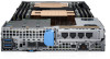
Figure 72. Installing the system battery Next steps 1. If removed, install the expansion card riser. 2. Follow the procedure listed in After working inside your system. 3. While booting, press F2 to enter System Setup and ensure that the battery is operating properly. 4. Enter the correct time and date in the System Setup Time and Date fields. 5. Exit System Setup. System board Removing the system board Prerequisites CAUTION: Do not attempt to remove the TPM plug-in module from the system board. Once the TPM plug-in module is installed, it is cryptographically bound to that specific system board. Any attempt to remove an installed TPM plug-in module breaks the cryptographic binding, and it cannot be reinstalled or installed on another system board. CAUTION: To avoid damage to the system board, ensure that the system board does not touch the side walls of the sled chassis, while sliding the system board into the sled. 1. Follow the safety guidelines listed in Safety instructions. 2. Follow the procedure listed in Before working inside your system. 3. Remove the sled from the chassis. 4. Remove the air shroud. 5. Remove the expansion card risers. 6. Remove the processor heat sink module. 7. Remove the memory modules. 8. If installed, remove OCP card. 9. If installed, remove the mezzanine card. 10. Remove the linking board 11. Disconnect all the cables from the system board. 12. Keep the Phillips #1 screwdriver and #4 nut driver ready. Steps 1. Remove the screws that secure the system board to the sled assembly. CAUTION: Do not lift the system board by holding a memory module slot, any other connector, or component. 2. Hold the system board by the edges, and lift the system board away from the sled. 118 Installing and removing enclosure components
-
 1
1 -
2
-
3
-
4
-
5
-
6
-
7
-
8
-
9
-
10
-
11
-
12
-
13
-
14
-
15
-
16
-
17
-
18
-
19
-
20
-
21
-
22
-
23
-
24
-
25
-
26
-
27
-
28
-
29
-
30
-
31
-
32
-
33
-
34
-
35
-
36
-
37
-
38
-
39
-
40
-
41
-
42
-
43
-
44
-
45
-
46
-
47
-
48
-
49
-
50
-
51
-
52
-
53
-
54
-
55
-
56
-
57
-
58
-
59
-
60
-
61
-
62
-
63
-
64
-
65
-
66
-
67
-
68
-
69
-
70
-
71
-
72
-
73
-
74
-
75
-
76
-
77
-
78
-
79
-
80
-
81
-
82
-
83
-
84
-
85
-
86
-
87
-
88
-
89
-
90
-
91
-
92
-
93
-
94
-
95
-
96
-
97
-
98
-
99
-
100
-
101
-
102
-
103
-
104
-
105
-
106
-
107
-
108
-
109
-
110
-
111
-
112
-
 113
113 -
 114
114 -
 115
115 -
 116
116 -
 117
117 -
 118
118 -
 119
119 -
 120
120 -
 121
121 -
 122
122 -
 123
123 -
124
-
125
-
126
-
127
-
128
-
129
 |
 |
