Dell PowerEdge C6420 EMC Installation and Service Manual - Page 78
Installing the linking board and PCIe cables
 |
View all Dell PowerEdge C6420 manuals
Add to My Manuals
Save this manual to your list of manuals |
Page 78 highlights
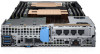
Figure 27. Removing the linking board and SATA cable Next steps 1. Install the linking board and PCIe cables. Installing the linking board and PCIe cables Prerequisites NOTE: Observe the routing of the cable as you remove it from the sled. Route the cable properly when you replace it to prevent the cable from being pinched or crimped. 1. Follow the safety guidelines listed in Safety instructions. Steps 1. Insert the PCIe_A connector into the connector on the system board, press the connector until it locks into place. 2. Insert and press the PCIe_B connector into the connector on the system board, press the connector until it locks into place. 3. If disconnected, reconnect the SATA cable to the x16 M.2 riser. 4. Using the Phillips #1 screwdriver, tighten the captive screws on the linking board to secure the board to the sled. 78 Installing and removing enclosure components
-
 1
1 -
2
-
3
-
4
-
5
-
6
-
7
-
8
-
9
-
10
-
11
-
12
-
13
-
14
-
15
-
16
-
17
-
18
-
19
-
20
-
21
-
22
-
23
-
24
-
25
-
26
-
27
-
28
-
29
-
30
-
31
-
32
-
33
-
34
-
35
-
36
-
37
-
38
-
39
-
40
-
41
-
42
-
43
-
44
-
45
-
46
-
47
-
48
-
49
-
50
-
51
-
52
-
53
-
54
-
55
-
56
-
57
-
58
-
59
-
60
-
61
-
62
-
63
-
64
-
65
-
66
-
67
-
68
-
69
-
70
-
71
-
72
-
 73
73 -
 74
74 -
 75
75 -
 76
76 -
 77
77 -
 78
78 -
 79
79 -
 80
80 -
 81
81 -
 82
82 -
 83
83 -
84
-
85
-
86
-
87
-
88
-
89
-
90
-
91
-
92
-
93
-
94
-
95
-
96
-
97
-
98
-
99
-
100
-
101
-
102
-
103
-
104
-
105
-
106
-
107
-
108
-
109
-
110
-
111
-
112
-
113
-
114
-
115
-
116
-
117
-
118
-
119
-
120
-
121
-
122
-
123
-
124
-
125
-
126
-
127
-
128
-
129
 |
 |
