Dell PowerEdge C6420 EMC Installation and Service Manual - Page 79
Processor and heat sink module
 |
View all Dell PowerEdge C6420 manuals
Add to My Manuals
Save this manual to your list of manuals |
Page 79 highlights
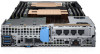
Figure 28. Installing the linking board and SATA cable Next steps 1. Install the support bracket. 2. Install the air shroud. 3. Follow the procedure listed in After working inside your system. Processor and heat sink module CAUTION: This is a Field Replaceable Unit (FRU). Removal and installation procedures must be performed only by Dell certified service technicians. NOTE: In a sled which has been configured with mixed CPUs - a fabric processor installed in the CPU2 socket and a non-fabric processor installed in the CPU1 socket, you must connect the external Omnipath link cables to Port 2 on the OCP carrier card. Use the following procedure when: • Removing and installing a heat sink • Replacing a processor Table 37. Supported heat sinks Heat sink Dimensions Design CPU 1, standard heat sink Length =108 mm (4.25 inches), Width =88 mm (3.46 inches), Height =24.8 mm (0.97 inches) 2 heat pipes CPU 1, extended heat sink Length =108 mm (4.25 inches), Width =96 mm (3.77 inches), Height =24.8 mm (0.97 inches) 2 heat pipes CPU 2, standard heat sink Length =108 mm (4.25 inches), Width =88 mm (3.46 inches), Height =24.8 mm (0.97 inches) 3 heat pipes Installing and removing enclosure components 79
-
 1
1 -
2
-
3
-
4
-
5
-
6
-
7
-
8
-
9
-
10
-
11
-
12
-
13
-
14
-
15
-
16
-
17
-
18
-
19
-
20
-
21
-
22
-
23
-
24
-
25
-
26
-
27
-
28
-
29
-
30
-
31
-
32
-
33
-
34
-
35
-
36
-
37
-
38
-
39
-
40
-
41
-
42
-
43
-
44
-
45
-
46
-
47
-
48
-
49
-
50
-
51
-
52
-
53
-
54
-
55
-
56
-
57
-
58
-
59
-
60
-
61
-
62
-
63
-
64
-
65
-
66
-
67
-
68
-
69
-
70
-
71
-
72
-
73
-
 74
74 -
 75
75 -
 76
76 -
 77
77 -
 78
78 -
 79
79 -
 80
80 -
 81
81 -
 82
82 -
 83
83 -
 84
84 -
85
-
86
-
87
-
88
-
89
-
90
-
91
-
92
-
93
-
94
-
95
-
96
-
97
-
98
-
99
-
100
-
101
-
102
-
103
-
104
-
105
-
106
-
107
-
108
-
109
-
110
-
111
-
112
-
113
-
114
-
115
-
116
-
117
-
118
-
119
-
120
-
121
-
122
-
123
-
124
-
125
-
126
-
127
-
128
-
129
 |
 |
