Dell PowerEdge C6420 EMC Installation and Service Manual - Page 95
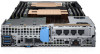
Removing the expansion card riser assembly
 |
View all Dell PowerEdge C6420 manuals
Add to My Manuals
Save this manual to your list of manuals |
Page 95 highlights
Table 39. Supported expansion cards (continued) Card type Form factor Link width QLogic 10G dual port V2 network card LP x8 QLogic 10G dual port SFP network card LP x8 QLogic 10G dual port SFP V2 network LP x8 card QLogic 25G quad port network card LP x8 QLogic 25G dual port SFP network card LP x8 QLogic dual port SFP V2 network card LP x8 BOSS card LP x8 Intel 25G dual port SFP network card LP x8 Mellanox single port PCIE network card LP x8 SATA X8 M.2 card N/A SATA X16 M.2 card N/A Intel 60-W FPGA card LP x16 Intel 70-W FPGA card LP x16 PM1725B 1.6 HHHL NVME card LP x8 PM1725B 3.2 HHHL NVME card LP x8 PM1725B 6.4 HHHL NVME card LP x8 P4800X 750GB HHHL PCIE card LP x8 Slot priority 4 4 4 4 4 4 5 4 4 4 4 4 4 4 4 Maximum number of cards 1 1 1 1 1 1 1 1 1 X8 PCIe Adapter (PCIe Bus Reserve for ESI) X16 PCIe Adapter (PCIe Bus Reserve for ESI) 1 1 1 1 1 1 Removing the expansion card riser assembly Prerequisites NOTE: Install an expansion card filler bracket over an empty expansion slot to maintain Federal Communications Commission (FCC) certification of the system. The brackets also keep dust and dirt out of the system and aid in proper cooling and airflow inside the system. 1. Follow the safety guidelines listed in Safety instructions. 2. Follow the procedure listed in Before working inside your system. Steps 1. Remove the screws that secure the expansion card riser assembly. 2. Lift the expansion card riser assembly out of the sled. Installing and removing enclosure components 95
-
 1
1 -
2
-
3
-
4
-
5
-
6
-
7
-
8
-
9
-
10
-
11
-
12
-
13
-
14
-
15
-
16
-
17
-
18
-
19
-
20
-
21
-
22
-
23
-
24
-
25
-
26
-
27
-
28
-
29
-
30
-
31
-
32
-
33
-
34
-
35
-
36
-
37
-
38
-
39
-
40
-
41
-
42
-
43
-
44
-
45
-
46
-
47
-
48
-
49
-
50
-
51
-
52
-
53
-
54
-
55
-
56
-
57
-
58
-
59
-
60
-
61
-
62
-
63
-
64
-
65
-
66
-
67
-
68
-
69
-
70
-
71
-
72
-
73
-
74
-
75
-
76
-
77
-
78
-
79
-
80
-
81
-
82
-
83
-
84
-
85
-
86
-
87
-
88
-
89
-
 90
90 -
 91
91 -
 92
92 -
 93
93 -
 94
94 -
 95
95 -
 96
96 -
 97
97 -
 98
98 -
 99
99 -
 100
100 -
101
-
102
-
103
-
104
-
105
-
106
-
107
-
108
-
109
-
110
-
111
-
112
-
113
-
114
-
115
-
116
-
117
-
118
-
119
-
120
-
121
-
122
-
123
-
124
-
125
-
126
-
127
-
128
-
129
 |
 |
