Dell PowerEdge C6420 EMC Installation and Service Manual - Page 70
System memory, System memory guidelines
 |
View all Dell PowerEdge C6420 manuals
Add to My Manuals
Save this manual to your list of manuals |
Page 70 highlights
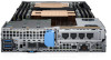
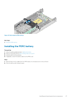
Figure 21. Installing the air shroud Next steps 1. If disconnected, connect the battery cable to the PERC card. 2. Follow the procedure listed in After working inside your system. System memory System memory guidelines The PowerEdge system supports DDR4 registered DIMMs (RDIMMs) and Load Reduced DIMMs (LRDIMMs). System memory holds the instructions that are executed by the processor. Your system contains 16 memory sockets that are split into two sets of 8 sockets, one set per processor. Each 8-socket set is organized into channels. In each channel, the release tabs of the first socket are marked white, the second socket black. Figure 22. Memory socket locations Memory channels are organized as follows: Table 34. Memory channels Processor Channel 0 Channel 1 Processor 1 Slots A1 and A7 Slots A2 Processor 2 Slots B1 and B7 Slots B2 Channel 2 Slots A3 Slots B3 Channel 3 Slots A8 and A4 Slots B8 and B4 Channel 4 Slots A5 Slots B5 Channel 5 Slots A6 Slots B6 70 Installing and removing enclosure components
-
 1
1 -
2
-
3
-
4
-
5
-
6
-
7
-
8
-
9
-
10
-
11
-
12
-
13
-
14
-
15
-
16
-
17
-
18
-
19
-
20
-
21
-
22
-
23
-
24
-
25
-
26
-
27
-
28
-
29
-
30
-
31
-
32
-
33
-
34
-
35
-
36
-
37
-
38
-
39
-
40
-
41
-
42
-
43
-
44
-
45
-
46
-
47
-
48
-
49
-
50
-
51
-
52
-
53
-
54
-
55
-
56
-
57
-
58
-
59
-
60
-
61
-
62
-
63
-
64
-
 65
65 -
 66
66 -
 67
67 -
 68
68 -
 69
69 -
 70
70 -
 71
71 -
 72
72 -
 73
73 -
 74
74 -
 75
75 -
76
-
77
-
78
-
79
-
80
-
81
-
82
-
83
-
84
-
85
-
86
-
87
-
88
-
89
-
90
-
91
-
92
-
93
-
94
-
95
-
96
-
97
-
98
-
99
-
100
-
101
-
102
-
103
-
104
-
105
-
106
-
107
-
108
-
109
-
110
-
111
-
112
-
113
-
114
-
115
-
116
-
117
-
118
-
119
-
120
-
121
-
122
-
123
-
124
-
125
-
126
-
127
-
128
-
129
 |
 |
