Dell PowerEdge R210 II Owner's Manual - Page 117
Table 6-2., System Board Jumpers and Connectors, Connector, Description, SATA connector C
 |
View all Dell PowerEdge R210 II manuals
Add to My Manuals
Save this manual to your list of manuals |
Page 117 highlights
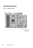
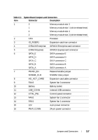
Table 6-2. System Board Jumpers and Connectors Item Connector Description 1 3 Memory module slot 3 1 Memory module slot 1 (white release lever) 4 Memory module slot 4 2 Memory module slot 2 (white release lever) 2 CPU Processor 3 IO_RISER1 Expansion-card riser connector 4 iDRAC6 Enterprise iDRAC6 Enterprise card connector 5 iDRAC6 Express iDRAC6 Express card connector 6 SATA_E SATA connector E SATA_D SATA connector D SATA_C SATA connector C SATA_B SATA connector B SATA_A SATA connector A 7 PWRD_EN Password enable jumper NVRAM_CLR NVRAM clear jumper 8 HD_ACT_CARD Expansion-card cable connector 9 FAN3 System fan 3 connector 10 Battery Battery socket 11 USB_CONN Internal USB connector 12 CTRL_PNL Control panel connector 13 FAN2 System fan 2 connector 14 FAN1 System fan 1 connector 15 12V 4-pin power connector 16 PWR_CONN 24-pin power connector Jumpers and Connectors 117
-
 1
1 -
2
-
3
-
4
-
5
-
6
-
7
-
8
-
9
-
10
-
11
-
12
-
13
-
14
-
15
-
16
-
17
-
18
-
19
-
20
-
21
-
22
-
23
-
24
-
25
-
26
-
27
-
28
-
29
-
30
-
31
-
32
-
33
-
34
-
35
-
36
-
37
-
38
-
39
-
40
-
41
-
42
-
43
-
44
-
45
-
46
-
47
-
48
-
49
-
50
-
51
-
52
-
53
-
54
-
55
-
56
-
57
-
58
-
59
-
60
-
61
-
62
-
63
-
64
-
65
-
66
-
67
-
68
-
69
-
70
-
71
-
72
-
73
-
74
-
75
-
76
-
77
-
78
-
79
-
80
-
81
-
82
-
83
-
84
-
85
-
86
-
87
-
88
-
89
-
90
-
91
-
92
-
93
-
94
-
95
-
96
-
97
-
98
-
99
-
100
-
101
-
102
-
103
-
104
-
105
-
106
-
107
-
108
-
109
-
110
-
111
-
 112
112 -
 113
113 -
 114
114 -
 115
115 -
 116
116 -
 117
117 -
 118
118 -
 119
119 -
 120
120 -
 121
121 -
 122
122 -
123
-
124
-
125
-
126
 |
 |
