Dell PowerEdge R210 II Owner's Manual - Page 81
Removing an iDRAC6 Enterprise Card, See Removing a VFlash Media Card
 |
View all Dell PowerEdge R210 II manuals
Add to My Manuals
Save this manual to your list of manuals |
Page 81 highlights
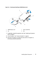
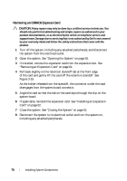
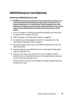
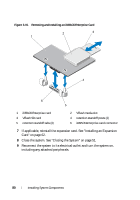
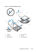
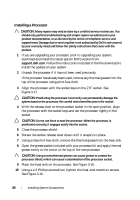
Removing an iDRAC6 Enterprise Card CAUTION: Many repairs may only be done by a certified service technician. You should only perform troubleshooting and simple repairs as authorized in your product documentation, or as directed by the online or telephone service and support team. Damage due to servicing that is not authorized by Dell is not covered by your warranty. Read and follow the safety instructions that came with the product. 1 Turn off the system, including any attached peripherals, and disconnect the system from the electrical outlet. 2 If present, disconnect the Ethernet cable from the iDRAC6 enterprise card connector on the system back panel. See Figure 1-2. 3 Open the system. See "Opening the System" on page 50. 4 If installed, remove the expansion card from the expansion-card slot. See "Removing an Expansion Card" on page 61. 5 Remove the VFlash media (if installed) from the iDRAC6 enterprise card. See "Removing a VFlash Media Card" on page 82. 6 Pull back slightly on the two tabs at the front edge of the card and gently lift the front edge of the card off of the retention standoffs. As the card releases from the standoffs, the connector under the card disengages from the system board connector. 7 Slide the card away from the back of the system until the RJ-45 connector is clear of the back panel, then lift the card out of the system. 8 If applicable, reinstall the expansion card. See "Installing an Expansion Card" on page 62. 9 Replace the plastic filler plug over the port at the system back panel. See "Back-Panel Features and Indicators" on page 14 for the port location. 10 Close the system. See "Closing the System" on page 51. 11 Reconnect the system to its electrical outlet and turn the system on, including any attached peripherals. Installing System Components 81
-
 1
1 -
2
-
3
-
4
-
5
-
6
-
7
-
8
-
9
-
10
-
11
-
12
-
13
-
14
-
15
-
16
-
17
-
18
-
19
-
20
-
21
-
22
-
23
-
24
-
25
-
26
-
27
-
28
-
29
-
30
-
31
-
32
-
33
-
34
-
35
-
36
-
37
-
38
-
39
-
40
-
41
-
42
-
43
-
44
-
45
-
46
-
47
-
48
-
49
-
50
-
51
-
52
-
53
-
54
-
55
-
56
-
57
-
58
-
59
-
60
-
61
-
62
-
63
-
64
-
65
-
66
-
67
-
68
-
69
-
70
-
71
-
72
-
73
-
74
-
75
-
 76
76 -
 77
77 -
 78
78 -
 79
79 -
 80
80 -
 81
81 -
 82
82 -
 83
83 -
 84
84 -
 85
85 -
 86
86 -
87
-
88
-
89
-
90
-
91
-
92
-
93
-
94
-
95
-
96
-
97
-
98
-
99
-
100
-
101
-
102
-
103
-
104
-
105
-
106
-
107
-
108
-
109
-
110
-
111
-
112
-
113
-
114
-
115
-
116
-
117
-
118
-
119
-
120
-
121
-
122
-
123
-
124
-
125
-
126
 |
 |
