Dell PowerEdge R210 II Owner's Manual - Page 94
shroud. See Removing the Cooling Shroud on, Disconnect all cables from the system board.
 |
View all Dell PowerEdge R210 II manuals
Add to My Manuals
Save this manual to your list of manuals |
Page 94 highlights
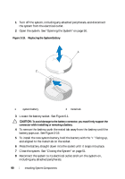
1 Turn off the system and attached peripherals, and disconnect the system from the electrical outlet. 2 Open the system. See "Opening the System" on page 50. 3 Remove the cooling shroud. See "Removing the Cooling Shroud" on page 67. 4 Remove any expansion card. See "Removing an Expansion Card" on page 61. 5 Remove the processor heat sink. See "Removing a Processor" on page 82. 6 If installed, remove the iDRAC6 Enterprise card. See "Removing an iDRAC6 Enterprise Card" on page 81. 7 If installed, remove the iDRAC6 Express card. See "Removing an iDRAC6 Express Card" on page 78. 8 Disconnect all cables from the system board. 9 Remove all the memory modules and memory blanks. See "Removing Memory Modules" on page 73. NOTE: To ensure proper reinstallation of memory modules, record the memory module socket locations. 10 Remove the ten screws securing the system board to the chassis and then slide the system board assembly toward the front end of the chassis. CAUTION: Do not lift the system board assembly by grasping a memory module, processor, or other components. 11 Grasp the system board assembly by its edges and lift the assembly away from the chassis. See Figure 3-21. 94 Installing System Components
-
 1
1 -
2
-
3
-
4
-
5
-
6
-
7
-
8
-
9
-
10
-
11
-
12
-
13
-
14
-
15
-
16
-
17
-
18
-
19
-
20
-
21
-
22
-
23
-
24
-
25
-
26
-
27
-
28
-
29
-
30
-
31
-
32
-
33
-
34
-
35
-
36
-
37
-
38
-
39
-
40
-
41
-
42
-
43
-
44
-
45
-
46
-
47
-
48
-
49
-
50
-
51
-
52
-
53
-
54
-
55
-
56
-
57
-
58
-
59
-
60
-
61
-
62
-
63
-
64
-
65
-
66
-
67
-
68
-
69
-
70
-
71
-
72
-
73
-
74
-
75
-
76
-
77
-
78
-
79
-
80
-
81
-
82
-
83
-
84
-
85
-
86
-
87
-
88
-
 89
89 -
 90
90 -
 91
91 -
 92
92 -
 93
93 -
 94
94 -
 95
95 -
 96
96 -
 97
97 -
 98
98 -
 99
99 -
100
-
101
-
102
-
103
-
104
-
105
-
106
-
107
-
108
-
109
-
110
-
111
-
112
-
113
-
114
-
115
-
116
-
117
-
118
-
119
-
120
-
121
-
122
-
123
-
124
-
125
-
126
 |
 |
