Dell PowerEdge R210 II Owner's Manual - Page 69
Installing the Cooling Shroud, System Memory, General Memory Module Installation Guidelines
 |
View all Dell PowerEdge R210 II manuals
Add to My Manuals
Save this manual to your list of manuals |
Page 69 highlights
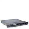
Installing the Cooling Shroud CAUTION: Many repairs may only be done by a certified service technician. You should only perform troubleshooting and simple repairs as authorized in your product documentation, or as directed by the online or telephone service and support team. Damage due to servicing that is not authorized by Dell is not covered by your warranty. Read and follow the safety instructions that came with the product. 1 Position the cooling shroud by aligning the guide slots with the guide screws on the system board. See Figure 3-11. 2 Push the cooling shroud down until all edges are secured to the system board. 3 Close the system. See "Opening and Closing the System" on page 50. System Memory Your system supports single- and dual-rank DDR3 unbuffered ECC DIMMs (UDIMMs). DIMMs can be 1066 or 1333 MHz. The system contains four memory sockets. Each two-socket set is organized into two channels. The first socket of each channel is marked with white release levers. General Memory Module Installation Guidelines To ensure optimal performance of your system, observe the following general guidelines when configuring your system memory. NOTE: Memory configurations that fail to observe these guidelines can prevent your system from starting and producing any video output. • Except for memory channels that are unused, all populated memory channels must have identical configurations. • Memory modules of different sizes can be mixed in sockets 1 to 4 (for example, 2 GB and 4 GB), but all populated channels must have identical configurations. • Memory modules are installed in the numeric order of the sockets beginning with 1 to 4. Installing System Components 69
-
 1
1 -
2
-
3
-
4
-
5
-
6
-
7
-
8
-
9
-
10
-
11
-
12
-
13
-
14
-
15
-
16
-
17
-
18
-
19
-
20
-
21
-
22
-
23
-
24
-
25
-
26
-
27
-
28
-
29
-
30
-
31
-
32
-
33
-
34
-
35
-
36
-
37
-
38
-
39
-
40
-
41
-
42
-
43
-
44
-
45
-
46
-
47
-
48
-
49
-
50
-
51
-
52
-
53
-
54
-
55
-
56
-
57
-
58
-
59
-
60
-
61
-
62
-
63
-
 64
64 -
 65
65 -
 66
66 -
 67
67 -
 68
68 -
 69
69 -
 70
70 -
 71
71 -
 72
72 -
 73
73 -
 74
74 -
75
-
76
-
77
-
78
-
79
-
80
-
81
-
82
-
83
-
84
-
85
-
86
-
87
-
88
-
89
-
90
-
91
-
92
-
93
-
94
-
95
-
96
-
97
-
98
-
99
-
100
-
101
-
102
-
103
-
104
-
105
-
106
-
107
-
108
-
109
-
110
-
111
-
112
-
113
-
114
-
115
-
116
-
117
-
118
-
119
-
120
-
121
-
122
-
123
-
124
-
125
-
126
 |
 |
