Dell PowerEdge SC1435 Hardware Owner's Manual - Page 12
Table 1-2., Front-Panel Indicators, Buttons, and Connectors, Indicator, Description, About Your System - diagnostic lights
 |
View all Dell PowerEdge SC1435 manuals
Add to My Manuals
Save this manual to your list of manuals |
Page 12 highlights
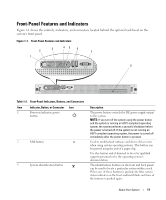
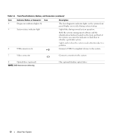
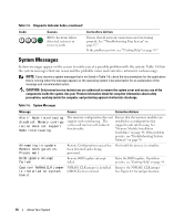
Table 1-2. Front-Panel Indicators, Buttons, and Connectors (continued) Item Indicator, Button, or Connector Icon 4 Diagnostics indicator lights (4) 5 System status indicator light 6 USB connectors (2) Description The four diagnostic indicator lights on the system front panel display error codes during system startup. Lights blue during normal system operation. Both the systems management software and the identification buttons located on the front and back of the system can cause the indicator to flash blue to identify a particular system. Lights amber when the system needs attention due to a problem. Connects USB 2.0-compliant devices to the system. 7 Video connector Connects a monitor to the system. 8 Optical drive (optional) NOTE: DVD devices are data only. One optional slimline optical drive 12 About Your System
-
 1
1 -
2
-
3
-
4
-
5
-
6
-
 7
7 -
 8
8 -
 9
9 -
 10
10 -
 11
11 -
 12
12 -
 13
13 -
 14
14 -
 15
15 -
 16
16 -
 17
17 -
18
-
19
-
20
-
21
-
22
-
23
-
24
-
25
-
26
-
27
-
28
-
29
-
30
-
31
-
32
-
33
-
34
-
35
-
36
-
37
-
38
-
39
-
40
-
41
-
42
-
43
-
44
-
45
-
46
-
47
-
48
-
49
-
50
-
51
-
52
-
53
-
54
-
55
-
56
-
57
-
58
-
59
-
60
-
61
-
62
-
63
-
64
-
65
-
66
-
67
-
68
-
69
-
70
-
71
-
72
-
73
-
74
-
75
-
76
-
77
-
78
-
79
-
80
-
81
-
82
-
83
-
84
-
85
-
86
-
87
-
88
-
89
-
90
-
91
-
92
-
93
-
94
-
95
-
96
-
97
-
98
-
99
-
100
-
101
-
102
-
103
-
104
-
105
-
106
-
107
-
108
-
109
-
110
-
111
-
112
-
113
-
114
-
115
-
116
-
117
-
118
-
119
-
120
-
121
-
122
-
123
-
124
-
125
-
126
-
127
-
128
-
129
-
130
-
131
-
132
 |
 |