Dell PowerEdge SC1435 Hardware Owner's Manual - Page 48
Non-Optimal Memory Configurations, Installing Memory Modules, configuration is non-optimal.
 |
View all Dell PowerEdge SC1435 manuals
Add to My Manuals
Save this manual to your list of manuals |
Page 48 highlights
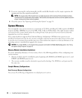
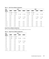
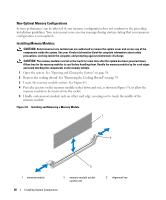
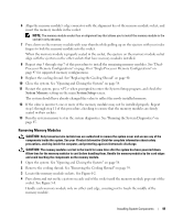
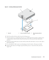
Non-Optimal Memory Configurations System performance can be affected if your memory configuration does not conform to the preceding installation guidelines. Your system may issue an error message during startup stating that your memory configuration is non-optimal. Installing Memory Modules CAUTION: Only trained service technicians are authorized to remove the system cover and access any of the components inside the system. See your Product Information Guide for complete information about safety precautions, working inside the computer, and protecting against electrostatic discharge. CAUTION: The memory modules are hot to the touch for some time after the system has been powered down. Allow time for the memory modules to cool before handling them. Handle the memory modules by the card edges and avoid touching the components on the memory module. 1 Open the system. See "Opening and Closing the System" on page 38. 2 Remove the cooling shroud. See "Removing the Cooling Shroud" on page 39. 3 Locate the memory module sockets. See Figure 6-2. 4 Press the ejectors on the memory module socket down and out, as shown in Figure 3-8, to allow the memory module to be inserted into the socket. 5 Handle each memory module only on either card edge, ensuring not to touch the middle of the memory module. Figure 3-8. Installing and Removing a Memory Module 1 2 3 1 memory module 2 memory module socket ejectors (2) 48 Installing System Components 3 alignment key
-
 1
1 -
2
-
3
-
4
-
5
-
6
-
7
-
8
-
9
-
10
-
11
-
12
-
13
-
14
-
15
-
16
-
17
-
18
-
19
-
20
-
21
-
22
-
23
-
24
-
25
-
26
-
27
-
28
-
29
-
30
-
31
-
32
-
33
-
34
-
35
-
36
-
37
-
38
-
39
-
40
-
41
-
42
-
 43
43 -
 44
44 -
 45
45 -
 46
46 -
 47
47 -
 48
48 -
 49
49 -
 50
50 -
 51
51 -
 52
52 -
 53
53 -
54
-
55
-
56
-
57
-
58
-
59
-
60
-
61
-
62
-
63
-
64
-
65
-
66
-
67
-
68
-
69
-
70
-
71
-
72
-
73
-
74
-
75
-
76
-
77
-
78
-
79
-
80
-
81
-
82
-
83
-
84
-
85
-
86
-
87
-
88
-
89
-
90
-
91
-
92
-
93
-
94
-
95
-
96
-
97
-
98
-
99
-
100
-
101
-
102
-
103
-
104
-
105
-
106
-
107
-
108
-
109
-
110
-
111
-
112
-
113
-
114
-
115
-
116
-
117
-
118
-
119
-
120
-
121
-
122
-
123
-
124
-
125
-
126
-
127
-
128
-
129
-
130
-
131
-
132
 |
 |
