Dell PowerEdge SC1435 Hardware Owner's Manual - Page 62
Installing the Control Panel, Connect the control panel cable to the control panel board.
 |
View all Dell PowerEdge SC1435 manuals
Add to My Manuals
Save this manual to your list of manuals |
Page 62 highlights
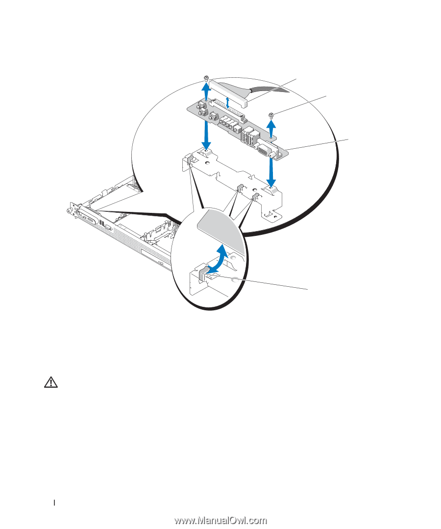
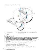
Figure 3-15. Control Panel Removal and Installation 3 1 2 3 4 1 control panel cable 4 tabs (3) 2 control-panel circuit board securing screws (2) 3 control panel circuit board Installing the Control Panel CAUTION: Only trained service technicians are authorized to remove the system cover and access any of the components inside the system. See your Product Information Guide for complete information about safety precautions, working inside the computer, and protecting against electrostatic discharge. 5 Place the new control panel board in the system and secure it with the two Phillips screws. See Figure 3-15. The front edge of the board fits under the three L-shaped tabs on the chassis. 6 Connect the control panel cable to the control panel board. 7 Close the system. See "Opening and Closing the System" on page 38. 8 Reconnect the system to the power source and turn on the system and attached peripherals. 62 Installing System Components
-
 1
1 -
2
-
3
-
4
-
5
-
6
-
7
-
8
-
9
-
10
-
11
-
12
-
13
-
14
-
15
-
16
-
17
-
18
-
19
-
20
-
21
-
22
-
23
-
24
-
25
-
26
-
27
-
28
-
29
-
30
-
31
-
32
-
33
-
34
-
35
-
36
-
37
-
38
-
39
-
40
-
41
-
42
-
43
-
44
-
45
-
46
-
47
-
48
-
49
-
50
-
51
-
52
-
53
-
54
-
55
-
56
-
 57
57 -
 58
58 -
 59
59 -
 60
60 -
 61
61 -
 62
62 -
 63
63 -
 64
64 -
 65
65 -
 66
66 -
 67
67 -
68
-
69
-
70
-
71
-
72
-
73
-
74
-
75
-
76
-
77
-
78
-
79
-
80
-
81
-
82
-
83
-
84
-
85
-
86
-
87
-
88
-
89
-
90
-
91
-
92
-
93
-
94
-
95
-
96
-
97
-
98
-
99
-
100
-
101
-
102
-
103
-
104
-
105
-
106
-
107
-
108
-
109
-
110
-
111
-
112
-
113
-
114
-
115
-
116
-
117
-
118
-
119
-
120
-
121
-
122
-
123
-
124
-
125
-
126
-
127
-
128
-
129
-
130
-
131
-
132
 |
 |