Dell PowerEdge SC1435 Hardware Owner's Manual - Page 52
Installing a Processor, See
 |
View all Dell PowerEdge SC1435 manuals
Add to My Manuals
Save this manual to your list of manuals |
Page 52 highlights
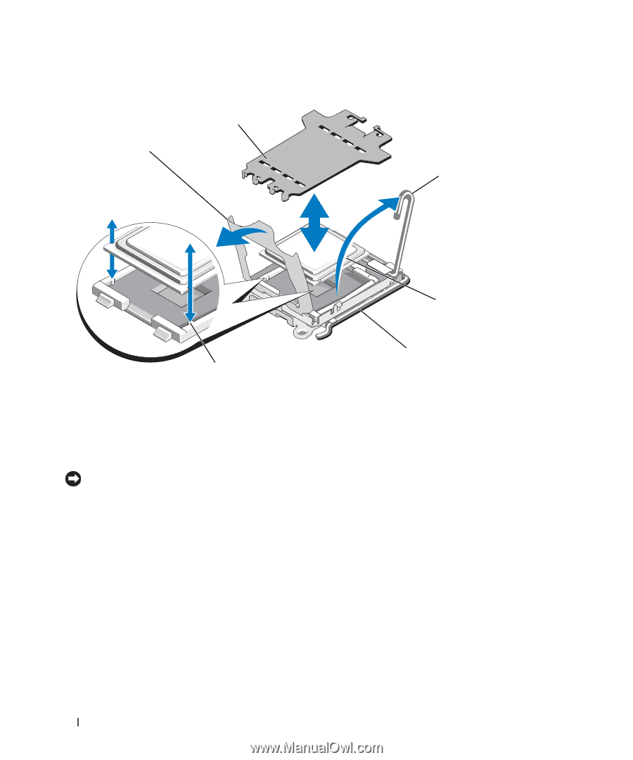
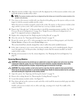
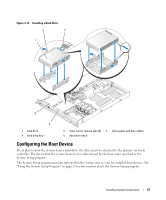
Figure 3-10. Installing and Removing the Processor 2 1 3 4 1 processor shield 4 processor 5 6 2 socket cover (remove before 3 socket-release lever adding second processor) 5 ZIF socket 6 socket key (2) 11 Open the processor shield and then lift the processor out of the socket. Leave the release lever up so that the socket is ready for the new processor. NOTICE: Be careful not to bend any of the pins on the LGA socket when removing the processor. Bending the pins can permanently damage the socket and system board. Installing a Processor 1 Unpack the new processor. 2 Align the processor with the socket keys on the ZIF socket. See Figure 3-10. 3 If you are adding a second processor to an empty socket, perform the following steps: a Remove the protective cover from the processor socket. See Figure 3-10. b Pull the socket-release lever 90 degrees upward. See Figure 3-10. c Lift the processor shield. See Figure 3-10. 52 Installing System Components
-
 1
1 -
2
-
3
-
4
-
5
-
6
-
7
-
8
-
9
-
10
-
11
-
12
-
13
-
14
-
15
-
16
-
17
-
18
-
19
-
20
-
21
-
22
-
23
-
24
-
25
-
26
-
27
-
28
-
29
-
30
-
31
-
32
-
33
-
34
-
35
-
36
-
37
-
38
-
39
-
40
-
41
-
42
-
43
-
44
-
45
-
46
-
 47
47 -
 48
48 -
 49
49 -
 50
50 -
 51
51 -
 52
52 -
 53
53 -
 54
54 -
 55
55 -
 56
56 -
 57
57 -
58
-
59
-
60
-
61
-
62
-
63
-
64
-
65
-
66
-
67
-
68
-
69
-
70
-
71
-
72
-
73
-
74
-
75
-
76
-
77
-
78
-
79
-
80
-
81
-
82
-
83
-
84
-
85
-
86
-
87
-
88
-
89
-
90
-
91
-
92
-
93
-
94
-
95
-
96
-
97
-
98
-
99
-
100
-
101
-
102
-
103
-
104
-
105
-
106
-
107
-
108
-
109
-
110
-
111
-
112
-
113
-
114
-
115
-
116
-
117
-
118
-
119
-
120
-
121
-
122
-
123
-
124
-
125
-
126
-
127
-
128
-
129
-
130
-
131
-
132
 |
 |