Dell PowerEdge SC1435 Hardware Owner's Manual - Page 46
System Memory, Memory Module Installation Guidelines, Sample Memory Configurations
 |
View all Dell PowerEdge SC1435 manuals
Add to My Manuals
Save this manual to your list of manuals |
Page 46 highlights
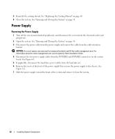
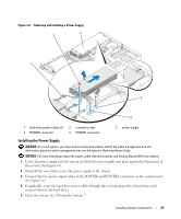
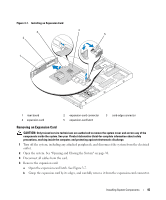
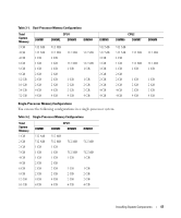
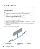
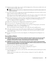
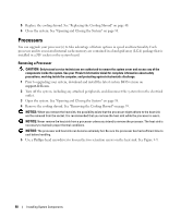
5 If you are removing the card permanently, install a metal filler bracket over the empty expansion slot opening and close the expansion-card latch. NOTE: You must install a filler bracket over an empty expansion slot to maintain Federal Communications Commission (FCC) certification of the system. The brackets also keep dust and dirt out of the system and aid in proper cooling and airflow inside the system. 6 Close the system. See "Opening and Closing the System" on page 38. System Memory You can upgrade your system memory to a maximum of 32 GB by installing 667-MHz registered DDR-II memory modules (DIMMs) in sets of 512-MB, 1-GB, 2-GB, or 4-GB modules. The eight memory sockets are located on the system board under the cooling shroud. Each processor has four memory channels, organized in sets of two channels. Your system hardware supports Non-Uniform Memory Architecture (NUMA) if two processors are installed. Each processor has its own memory controller and local memory for reduced access times, but it can also access memory from another processor. This architecture improves system performance if an operating system is installed that supports this feature. NOTICE: To enable NUMA, run the System Setup program and disable the Node Interleaving option. See "Using the System Setup Program" on page 23. Memory Module Installation Guidelines To ensure optimal performance of your system, observe the following guidelines when configuring your system memory. • Memory modules must be installed in pairs, beginning with DIMM1 and DIMM2 (processor 1), and DIMM5 and DIMM6 (processor 2). • The memory modules must be identical in speed and technology. The DIMMs in each pair must be the same size. Sample Memory Configurations Dual-Processor Memory Configurations You can use the following configurations in a dual-processor system. 46 Installing System Components
-
 1
1 -
2
-
3
-
4
-
5
-
6
-
7
-
8
-
9
-
10
-
11
-
12
-
13
-
14
-
15
-
16
-
17
-
18
-
19
-
20
-
21
-
22
-
23
-
24
-
25
-
26
-
27
-
28
-
29
-
30
-
31
-
32
-
33
-
34
-
35
-
36
-
37
-
38
-
39
-
40
-
 41
41 -
 42
42 -
 43
43 -
 44
44 -
 45
45 -
 46
46 -
 47
47 -
 48
48 -
 49
49 -
 50
50 -
 51
51 -
52
-
53
-
54
-
55
-
56
-
57
-
58
-
59
-
60
-
61
-
62
-
63
-
64
-
65
-
66
-
67
-
68
-
69
-
70
-
71
-
72
-
73
-
74
-
75
-
76
-
77
-
78
-
79
-
80
-
81
-
82
-
83
-
84
-
85
-
86
-
87
-
88
-
89
-
90
-
91
-
92
-
93
-
94
-
95
-
96
-
97
-
98
-
99
-
100
-
101
-
102
-
103
-
104
-
105
-
106
-
107
-
108
-
109
-
110
-
111
-
112
-
113
-
114
-
115
-
116
-
117
-
118
-
119
-
120
-
121
-
122
-
123
-
124
-
125
-
126
-
127
-
128
-
129
-
130
-
131
-
132
 |
 |