Dell PowerEdge SC1435 Hardware Owner's Manual - Page 64
Installing a System Board, Cooling Fan Module
 |
View all Dell PowerEdge SC1435 manuals
Add to My Manuals
Save this manual to your list of manuals |
Page 64 highlights
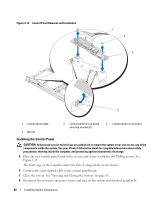
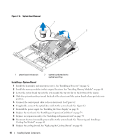
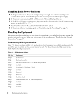
Figure 3-16. System Board Removal 1 1 2 2 1 system board release pin 2 system board attached to system-board tray Installing a System Board 1 Install the heatsink(s) and microprocessor(s). See "Installing a Processor" on page 52 2 Install the memory modules in their original locations. See "Installing Memory Modules" on page 48. 3 Lower the system-board tray into the system until the tray sits flat on the bottom of the chassis. 4 Slide the system-board tray toward the back of the chassis until the system board release pin locks into position. 5 Connect the control panel cable to the system board. See Figure 6-2. 6 If applicable, connect the optical drive cable to the system board. See Figure 6-2. 7 Reinstall the power supply. See "Installing the Power Supply" on page 43. 8 Replace the riser board. See "Installing an Expansion-Card Riser" on page 59. 9 Replace any expansion card(s). See "Installing an Expansion Card" on page 44. 10 Reconnect the two fan module power cables to the system board. See "Removing and Installing a Cooling Fan Module" on page 41. 11 Replace the cooling shroud. See "Replacing the Cooling Shroud" on page 40. 64 Installing System Components
-
 1
1 -
2
-
3
-
4
-
5
-
6
-
7
-
8
-
9
-
10
-
11
-
12
-
13
-
14
-
15
-
16
-
17
-
18
-
19
-
20
-
21
-
22
-
23
-
24
-
25
-
26
-
27
-
28
-
29
-
30
-
31
-
32
-
33
-
34
-
35
-
36
-
37
-
38
-
39
-
40
-
41
-
42
-
43
-
44
-
45
-
46
-
47
-
48
-
49
-
50
-
51
-
52
-
53
-
54
-
55
-
56
-
57
-
58
-
 59
59 -
 60
60 -
 61
61 -
 62
62 -
 63
63 -
 64
64 -
 65
65 -
 66
66 -
 67
67 -
 68
68 -
 69
69 -
70
-
71
-
72
-
73
-
74
-
75
-
76
-
77
-
78
-
79
-
80
-
81
-
82
-
83
-
84
-
85
-
86
-
87
-
88
-
89
-
90
-
91
-
92
-
93
-
94
-
95
-
96
-
97
-
98
-
99
-
100
-
101
-
102
-
103
-
104
-
105
-
106
-
107
-
108
-
109
-
110
-
111
-
112
-
113
-
114
-
115
-
116
-
117
-
118
-
119
-
120
-
121
-
122
-
123
-
124
-
125
-
126
-
127
-
128
-
129
-
130
-
131
-
132
 |
 |
