Dell PowerEdge SC1435 Hardware Owner's Manual - Page 16
System Messages - bios
 |
View all Dell PowerEdge SC1435 manuals
Add to My Manuals
Save this manual to your list of manuals |
Page 16 highlights
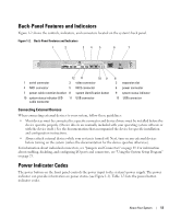
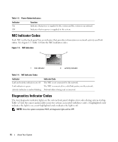
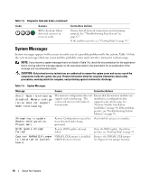
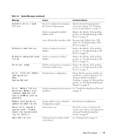
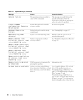
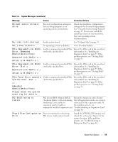
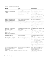
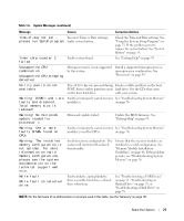
Table 1-5. Diagnostic Indicator Codes (continued) Code Causes BIOS checksum failure detected; system is in recovery mode. Corrective Action Ensure that all network connections are functioning properly. See ""Troubleshooting Your System" on page 67." If the problem persists, see ""Getting Help" on page 95." System Messages System messages appear on the screen to notify you of a possible problem with the system. Table 1-6 lists the system messages that can occur and the probable cause and corrective action for each message. NOTE: If you receive a system message that is not listed in Table 1-6, check the documentation for the application that is running when the message appears or the operating system's documentation for an explanation of the message and recommended action. CAUTION: Only trained service technicians are authorized to remove the system cover and access any of the components inside the system. See your Product Information Guide for complete information about safety precautions, working inside the computer, and protecting against electrostatic discharge. Table 1-6. System Messages Message Causes Corrective Actions Alert! Node Interleaving The memory configuration does not Ensure that the memory modules are disabled! Memory configu- support node interleaving. The ration does not support system will run but with reduced Node Interleaving. functionality. installed in a configuration that supports node interleaving. See "Memory Module Installation Guidelines" on page 46. If the problem persists, see "Troubleshooting System Memory" on page 76. Attempting to update Remote Configuration. Please wait... Remote Configuration request has Wait until the process is complete. been detected and is being processed. BIOS Update Attempt Failed! Remote BIOS update attempt failed. Retry the BIOS update. If problem persists, see "Getting Help" on page 95. Caution! NVRAM_CLR jumper NVRAM_CLR jumper is installed. Remove the NVRAM_CLR jumper. is installed on system CMOS has been cleared. See Figure 6-1 for jumper location. board. 16 About Your System
-
 1
1 -
2
-
3
-
4
-
5
-
6
-
7
-
8
-
9
-
10
-
 11
11 -
 12
12 -
 13
13 -
 14
14 -
 15
15 -
 16
16 -
 17
17 -
 18
18 -
 19
19 -
 20
20 -
 21
21 -
22
-
23
-
24
-
25
-
26
-
27
-
28
-
29
-
30
-
31
-
32
-
33
-
34
-
35
-
36
-
37
-
38
-
39
-
40
-
41
-
42
-
43
-
44
-
45
-
46
-
47
-
48
-
49
-
50
-
51
-
52
-
53
-
54
-
55
-
56
-
57
-
58
-
59
-
60
-
61
-
62
-
63
-
64
-
65
-
66
-
67
-
68
-
69
-
70
-
71
-
72
-
73
-
74
-
75
-
76
-
77
-
78
-
79
-
80
-
81
-
82
-
83
-
84
-
85
-
86
-
87
-
88
-
89
-
90
-
91
-
92
-
93
-
94
-
95
-
96
-
97
-
98
-
99
-
100
-
101
-
102
-
103
-
104
-
105
-
106
-
107
-
108
-
109
-
110
-
111
-
112
-
113
-
114
-
115
-
116
-
117
-
118
-
119
-
120
-
121
-
122
-
123
-
124
-
125
-
126
-
127
-
128
-
129
-
130
-
131
-
132
 |
 |