Dell PowerEdge SC1435 Hardware Owner's Manual - Page 40
Replacing the Cooling Shroud, Cooling Fan Modules, Removing a Cooling Fan Module
 |
View all Dell PowerEdge SC1435 manuals
Add to My Manuals
Save this manual to your list of manuals |
Page 40 highlights
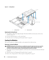
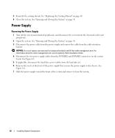
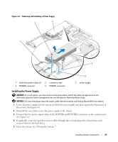
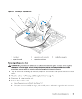
Figure 3-4. Cooling Shroud 1 2 1 cooling shroud 2 locator pins (6) Replacing the Cooling Shroud 1 To install the cooling shroud, align the edges of the shroud with the six locator pins on the system board. See Figure 3-4. 2 Lower the shroud into place over the system board. 3 Close the system. See "Opening and Closing the System" on page 38. Cooling Fan Modules This system contains two cooling fan modules, each comprised of two dual-rotor fans. Removing a Cooling Fan Module CAUTION: Only trained service technicians are authorized to remove the system cover and access any of the components inside the system. See your Product Information Guide for complete information about safety precautions, working inside the computer, and protecting against electrostatic discharge. 1 Turn off the system and attached peripherals, and disconnect the system from the electrical outlet and peripherals. 2 Open the system. See "Opening and Closing the System" on page 38. 3 Remove the cooling shroud. See "Removing the Cooling Shroud" on page 39. 40 Installing System Components
-
 1
1 -
2
-
3
-
4
-
5
-
6
-
7
-
8
-
9
-
10
-
11
-
12
-
13
-
14
-
15
-
16
-
17
-
18
-
19
-
20
-
21
-
22
-
23
-
24
-
25
-
26
-
27
-
28
-
29
-
30
-
31
-
32
-
33
-
34
-
 35
35 -
 36
36 -
 37
37 -
 38
38 -
 39
39 -
 40
40 -
 41
41 -
 42
42 -
 43
43 -
 44
44 -
 45
45 -
46
-
47
-
48
-
49
-
50
-
51
-
52
-
53
-
54
-
55
-
56
-
57
-
58
-
59
-
60
-
61
-
62
-
63
-
64
-
65
-
66
-
67
-
68
-
69
-
70
-
71
-
72
-
73
-
74
-
75
-
76
-
77
-
78
-
79
-
80
-
81
-
82
-
83
-
84
-
85
-
86
-
87
-
88
-
89
-
90
-
91
-
92
-
93
-
94
-
95
-
96
-
97
-
98
-
99
-
100
-
101
-
102
-
103
-
104
-
105
-
106
-
107
-
108
-
109
-
110
-
111
-
112
-
113
-
114
-
115
-
116
-
117
-
118
-
119
-
120
-
121
-
122
-
123
-
124
-
125
-
126
-
127
-
128
-
129
-
130
-
131
-
132
 |
 |
