Dell Studio Hybrid D140G Studio Hybrid Service Manual - Page 11
Installing the Riser Card
 |
View all Dell Studio Hybrid D140G manuals
Add to My Manuals
Save this manual to your list of manuals |
Page 11 highlights
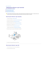
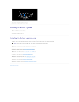
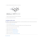
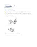
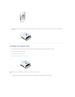
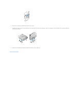
6. Disconnect the side logo cable from the connector on the drive cage. 1 drive cage 3 side logo connector 2 riser card 7. Remove the two screws that secures the riser card to the drive cage. 8. Lift the riser card away from the drive cage. Installing the Riser Card NOTICE: The connectors are keyed to ensure the card fits correctly. If the card is not fitting properly, position the card so that the connectors on the card and on the system board are aligned correctly. 1. Follow the procedure in Before You Begin. 2. Slide the riser card below the clamp on the drive cage. Align the holes on the riser card with the holes on the drive cage. 3. Tighten the screws to secure the riser card to the drive cage. 4. Connect the side logo connector to the drive cage. 5. Replace the hard drive (see Installing the Hard Drive). 6. Replace the optical drive (see Installing the Optical Drive). 7. Replace the drive cage (see Installing the Drive Cage). 8. Replace the computer cover (see Installing the Computer Cover). Back to Contents Page
-
 1
1 -
2
-
3
-
4
-
5
-
 6
6 -
 7
7 -
 8
8 -
 9
9 -
 10
10 -
 11
11 -
 12
12 -
 13
13 -
 14
14 -
 15
15 -
 16
16 -
17
-
18
-
19
-
20
-
21
-
22
-
23
-
24
-
25
-
26
-
27
-
28
-
29
-
30
-
31
-
32
-
33
-
34
-
35
-
36
-
37
-
38
-
39
-
40
-
41
-
42
 |
 |
