Dell Studio Hybrid D140G Studio Hybrid Service Manual - Page 38
Replacing the System Board
 |
View all Dell Studio Hybrid D140G manuals
Add to My Manuals
Save this manual to your list of manuals |
Page 38 highlights
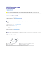
Back to Contents Page Replacing the System Board Dell™ Studio Hybrid Service Manual Removing the System Board Installing the System Board CAUTION: Before working inside your computer, read the safety information that shipped with your computer. For additional safety best practices information, see the Regulatory Compliance Homepage at www.dell.com/regulatory_compliance. Removing the System Board 1. Follow the procedures in Before You Begin. 2. Remove the computer cover (see Removing the Computer Cover). 3. Remove the drive cage (see Removing the Drive Cage). CAUTION: The processor heat sink can get very hot during normal operation. Be sure that the heat sink has had sufficient time to cool before you touch it. 4. Remove the processor heat sink (see Removing the Heat Sink). 5. Remove all the cards (see Replacing Cards). NOTE: If the WLAN card or the Blu-ray decode acceleration card is not installed, ensure that you remove the screws that are used to hold down the cards. 6. Remove the back panel (see Removing the Back Panel). 7. Remove any additional components that may restrict access to the system board. NOTICE: Carefully note the routing and location of each cable before you disconnect it, so that you are sure to re-route cables correctly. An incorrectly routed or a disconnected cable could lead to computer problems. 8. Disconnect the cables as shown below: 1 front panel connector (F_PANEL_CON1) 2 RF KB/Mouse receiver module connector (RF_KB/MS) riser card 3 battery connector (BATCON1) 4 touch panel board connector (TPB_CON1) 5 WLAN card /Blu-ray decode acceleration card screws (2) 6 side logo connector (S_LOGO_CON1) 9. Remove the screws that secure the system board to the chassis.
-
 1
1 -
2
-
3
-
4
-
5
-
6
-
7
-
8
-
9
-
10
-
11
-
12
-
13
-
14
-
15
-
16
-
17
-
18
-
19
-
20
-
21
-
22
-
23
-
24
-
25
-
26
-
27
-
28
-
29
-
30
-
31
-
32
-
 33
33 -
 34
34 -
 35
35 -
 36
36 -
 37
37 -
 38
38 -
 39
39 -
 40
40 -
 41
41 -
 42
42
 |
 |
