Dell Studio Hybrid D140G Studio Hybrid Service Manual - Page 28
Replacing the Processor
 |
View all Dell Studio Hybrid D140G manuals
Add to My Manuals
Save this manual to your list of manuals |
Page 28 highlights
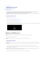
Back to Contents Page Replacing the Processor Dell™ Studio Hybrid Service Manual Removing the Processor Installing the Processor CAUTION: Before working inside your computer, read the safety information that shipped with your computer. For additional safety best practices information, see the Regulatory Compliance Homepage at www.dell.com/regulatory_compliance. NOTICE: Do not perform the following steps unless you are familiar with hardware removal and replacement. Performing these steps incorrectly could damage your system board. For technical service, see "Contacting Dell" in your Setup Guide. Removing the Processor 1. Follow the procedures in Before You Begin. 2. Remove the computer cover (see Removing the Computer Cover). 3. Remove the drive cage (see Removing the Drive Cage). 4. Remove the processor heat sink (see Removing the Heat Sink). 5. The ZIF-socket cam screw secures the processor to the system board. To loosen the ZIF socket, use a small, flat-blade screwdriver and rotate the ZIFsocket cam screw counterclockwise until it comes to the cam stop. 1 processor 3 ZIF-socket cam screw 2 ZIF socket 4 pin-1 corner of processor NOTE: Ensure that the arrow on the ZIF-socket cam screw is in the open position before you pull out the processor. 6. Lift the processor away from the socket. NOTE: When removing the processor, pull it straight up. Be careful not to bend the pins on the processor. Installing the Processor NOTICE: Ensure that the cam lock is in the fully open position before seating the processor. Seating the processor properly in the ZIF socket does not require force. NOTICE: A processor that is not properly seated can result in an intermittent connection or permanent damage to the processor and ZIF socket. 1. Align the pin-1 corner of the processor so that it points to the triangle on the ZIF socket, and insert the processor into the ZIF socket. When the processor is correctly seated, all four corners are aligned at the same height. If one or more corners of the processor are higher than the others, the processor is not seated correctly. NOTICE: To prevent intermittent contact between the ZIF-socket cam screw and the processor when removing or replacing the processor, press to apply slight pressure to the center of the processor while turning the cam screw. 2. Tighten the ZIF socket by turning the cam screw clockwise to secure the processor to the system board.
-
 1
1 -
2
-
3
-
4
-
5
-
6
-
7
-
8
-
9
-
10
-
11
-
12
-
13
-
14
-
15
-
16
-
17
-
18
-
19
-
20
-
21
-
22
-
 23
23 -
 24
24 -
 25
25 -
 26
26 -
 27
27 -
 28
28 -
 29
29 -
 30
30 -
 31
31 -
 32
32 -
 33
33 -
34
-
35
-
36
-
37
-
38
-
39
-
40
-
41
-
42
 |
 |
