Dell Studio Hybrid D140G Studio Hybrid Service Manual - Page 26
Replacing the Power Switch Assembly
 |
View all Dell Studio Hybrid D140G manuals
Add to My Manuals
Save this manual to your list of manuals |
Page 26 highlights
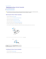
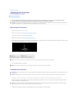
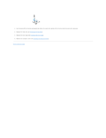
Back to Contents Page Replacing the Power Switch Assembly Dell™ Studio Hybrid Service Manual Removing the Power Switch Assembly Installing the Power Switch Assembly CAUTION: Before working inside your computer, read the safety information that shipped with your computer. For additional safety best practices information, see the Regulatory Compliance Homepage at www.dell.com/regulatory_compliance. Removing the Power Switch Assembly 1. Follow the procedure in Before You Begin. 2. Remove the computer cover (see Removing the Computer Cover). 3. Remove the drive cage (see Removing the Drive Cage). 4. Remove the front panel (see Removing the Front I/O Panel). 5. Remove the RF receiver board (see Removing the RF Receiver Board). 6. Disconnect the power cable from the system board( F_PANEL_CON1). 7. Press the latches on either side of the power switch holder and push the power switch holder towards the front of the chassis. 8. Remove the power switch and the LED from the power switch holder as shown below. 1 LED 3 power switch holder 2 power switch Installing the Power Switch Assembly 1. Follow the procedure in Before You Begin. 2. Replace the power switch and the LED into the power switch holder.
-
 1
1 -
2
-
3
-
4
-
5
-
6
-
7
-
8
-
9
-
10
-
11
-
12
-
13
-
14
-
15
-
16
-
17
-
18
-
19
-
20
-
 21
21 -
 22
22 -
 23
23 -
 24
24 -
 25
25 -
 26
26 -
 27
27 -
 28
28 -
 29
29 -
 30
30 -
 31
31 -
32
-
33
-
34
-
35
-
36
-
37
-
38
-
39
-
40
-
41
-
42
 |
 |
