Dell XPS Owners Manual - Page 94
Battery, Replacing the Battery
 |
View all Dell XPS manuals
Add to My Manuals
Save this manual to your list of manuals |
Page 94 highlights
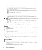
2 Remove the existing modem: a Remove the modem cable from the RJ11 internal connector. b Use a small Phillips screwdriver to remove the two screws securing the modem to the system board, and set the screws aside. c Pull straight up on the attached pull-tab to lift the modem out of its connector on the system board. d Remove the modem cable from the modem. 3 Install the new modem: a Replace the T-shaped connector of the modem cable to the modem. b Align the modem with the screw holes and press the modem into its connector on the system board. NOTICE: The connectors are keyed to ensure correct insertion. If you feel resistance, check the connectors and realign the card. c Use a Phillips screwdriver to replace and tighten the two screws that secure the modem to the system board. d Replace the other end of the modem cable to the RJ11 internal connector. 4 Replace the computer cover (see "Replacing the Computer Cover" on page 96). Battery CAUTION: Before you begin any of the procedures in this section, follow the safety instructions located in the Product Information Guide. NOTICE: To prevent static damage to components inside your computer, discharge static electricity from your body before you touch any of your computer's electronic components. You can do so by touching an unpainted metal surface on the computer chassis. A coin-cell battery maintains computer configuration, date, and time information. The battery can last several years. If you have to repeatedly reset time and date information after turning on the computer, replace the battery. CAUTION: A new battery can explode if it is incorrectly installed. Replace the battery only with the same or equivalent type recommended by the manufacturer. Discard used batteries according to the manufacturer's instructions. Replacing the Battery NOTE: For information regarding the type of coin-cell battery, see "Power" on page 100. 1 Record all the screens in system setup (see "System Setup" on page 101) so that you can restore the correct settings in step 9. 2 Follow the procedures in "Before You Begin" on page 61. 94 Removing and Installing Parts
-
 1
1 -
2
-
3
-
4
-
5
-
6
-
7
-
8
-
9
-
10
-
11
-
12
-
13
-
14
-
15
-
16
-
17
-
18
-
19
-
20
-
21
-
22
-
23
-
24
-
25
-
26
-
27
-
28
-
29
-
30
-
31
-
32
-
33
-
34
-
35
-
36
-
37
-
38
-
39
-
40
-
41
-
42
-
43
-
44
-
45
-
46
-
47
-
48
-
49
-
50
-
51
-
52
-
53
-
54
-
55
-
56
-
57
-
58
-
59
-
60
-
61
-
62
-
63
-
64
-
65
-
66
-
67
-
68
-
69
-
70
-
71
-
72
-
73
-
74
-
75
-
76
-
77
-
78
-
79
-
80
-
81
-
82
-
83
-
84
-
85
-
86
-
87
-
88
-
 89
89 -
 90
90 -
 91
91 -
 92
92 -
 93
93 -
 94
94 -
 95
95 -
 96
96 -
 97
97 -
 98
98 -
 99
99 -
100
-
101
-
102
-
103
-
104
-
105
-
106
-
107
-
108
-
109
-
110
-
111
-
112
-
113
-
114
-
115
-
116
-
117
-
118
-
119
-
120
-
121
-
122
-
123
-
124
-
125
-
126
-
127
-
128
-
129
-
130
-
131
-
132
-
133
-
134
-
135
-
136
 |
 |
