Epson TM-L90 Technical Reference - Page 36
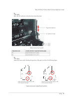
disconnected from the wall outlet; then grasp the arrow marked of the connector and pull
 |
View all Epson TM-L90 manuals
Add to My Manuals
Save this manual to your list of manuals |
Page 36 highlights
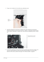
3. Remove the bottom of the cover as shown in the illustration below. 4. Install the connector of the DC cable onto the DC connector (labeled DC24V). Power supply connector Power Supply Connector Note: The connector panel varies depending on the models. When removing the DC cable connector from the printer, first confirm that the AC cable has been disconnected from the wall outlet; then grasp the arrow marked section of the connector and pull straight out. 2.4.2 Caution about AC adapter and Supply Voltage ❏ ERROR LED flashes when a high voltage or low voltage error occurs. In such cases, immediately turn the power off. Refer to "Unrecoverable errors" on page 116 for the LED flashing patterns. 36 Setup
-
 1
1 -
2
-
3
-
4
-
5
-
6
-
7
-
8
-
9
-
10
-
11
-
12
-
13
-
14
-
15
-
16
-
17
-
18
-
19
-
20
-
21
-
22
-
23
-
24
-
25
-
26
-
27
-
28
-
29
-
30
-
 31
31 -
 32
32 -
 33
33 -
 34
34 -
 35
35 -
 36
36 -
 37
37 -
 38
38 -
 39
39 -
 40
40 -
 41
41 -
42
-
43
-
44
-
45
-
46
-
47
-
48
-
49
-
50
-
51
-
52
-
53
-
54
-
55
-
56
-
57
-
58
-
59
-
60
-
61
-
62
-
63
-
64
-
65
-
66
-
67
-
68
-
69
-
70
-
71
-
72
-
73
-
74
-
75
-
76
-
77
-
78
-
79
-
80
-
81
-
82
-
83
-
84
-
85
-
86
-
87
-
88
-
89
-
90
-
91
-
92
-
93
-
94
-
95
-
96
-
97
-
98
-
99
-
100
-
101
-
102
-
103
-
104
-
105
-
106
-
107
-
108
-
109
-
110
-
111
-
112
-
113
-
114
-
115
-
116
-
117
-
118
-
119
-
120
-
121
-
122
-
123
-
124
-
125
-
126
-
127
-
128
-
129
-
130
-
131
-
132
-
133
-
134
-
135
-
136
-
137
-
138
-
139
-
140
-
141
-
142
-
143
-
144
-
145
-
146
-
147
-
148
-
149
-
150
-
151
-
152
-
153
-
154
-
155
-
156
-
157
-
158
-
159
-
160
-
161
-
162
-
163
-
164
-
165
-
166
-
167
-
168
-
169
-
170
-
171
-
172
-
173
-
174
-
175
-
176
-
177
-
178
-
179
-
180
-
181
-
182
-
183
-
184
-
185
-
186
-
187
-
188
-
189
-
190
-
191
-
192
-
193
-
194
-
195
-
196
-
197
-
198
-
199
-
200
-
201
-
202
-
203
-
204
-
205
-
206
-
207
-
208
-
209
-
210
-
211
-
212
 |
 |

36
Setup
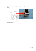
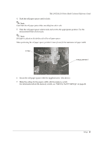
3.
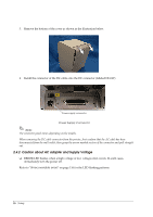
Remove the bottom of the cover as shown in the illustration below.
4.
Install the connector of the DC cable onto the DC connector (labeled DC24V).
Power Supply Connector
Note:
The connector panel varies depending on the models.
When removing the DC cable connector from the printer, first confirm that the AC cable has been
disconnected from the wall outlet; then grasp the arrow marked section of the connector and pull straight
out.
2.4.2
Caution about AC adapter and Supply Voltage
❏
ERROR LED flashes when a high voltage or low voltage error occurs. In such cases,
immediately turn the power off.
Refer to "
Unrecoverable errors
" on page 116 for the LED flashing patterns.
Power supply connector