Epson TM-L90 Technical Reference - Page 65
Connecting to the Host Computer and Options
 |
View all Epson TM-L90 manuals
Add to My Manuals
Save this manual to your list of manuals |
Page 65 highlights
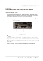
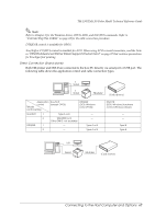
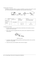
TM-L90/TM-L90 Peeler Model Technical Reference Guide Chapter 3 Connecting to the Host Computer and Options 3.1 Connecting the Cable This printer has 5 types of interface, serial, parallel, USB, Ethernet, and wireless LAN. The method of connecting such options as a customer display varies depending on the interface type. Note that some interfaces do not accept specific connection methods. All cables are connected to the connector panel located on the lower rear side of the printer. Drawer kick connector Power supply connector Interface connector Connector Panel Note: The figure above shows the connector panel for RS-232 interface model printer (TM-L90 other than 4** models, TM-L90 Peeler other than 39* models). The shape of the interface connector varies according to the type of interface used. Be sure to turn off the power supply for both the printer and the host computer unit before connecting the various cables. Be sure to unplug the power cord before inserting or removing the interface board. Connecting to the Host Computer and Options 65
-
 1
1 -
2
-
3
-
4
-
5
-
6
-
7
-
8
-
9
-
10
-
11
-
12
-
13
-
14
-
15
-
16
-
17
-
18
-
19
-
20
-
21
-
22
-
23
-
24
-
25
-
26
-
27
-
28
-
29
-
30
-
31
-
32
-
33
-
34
-
35
-
36
-
37
-
38
-
39
-
40
-
41
-
42
-
43
-
44
-
45
-
46
-
47
-
48
-
49
-
50
-
51
-
52
-
53
-
54
-
55
-
56
-
57
-
58
-
59
-
 60
60 -
 61
61 -
 62
62 -
 63
63 -
 64
64 -
 65
65 -
 66
66 -
 67
67 -
 68
68 -
 69
69 -
 70
70 -
71
-
72
-
73
-
74
-
75
-
76
-
77
-
78
-
79
-
80
-
81
-
82
-
83
-
84
-
85
-
86
-
87
-
88
-
89
-
90
-
91
-
92
-
93
-
94
-
95
-
96
-
97
-
98
-
99
-
100
-
101
-
102
-
103
-
104
-
105
-
106
-
107
-
108
-
109
-
110
-
111
-
112
-
113
-
114
-
115
-
116
-
117
-
118
-
119
-
120
-
121
-
122
-
123
-
124
-
125
-
126
-
127
-
128
-
129
-
130
-
131
-
132
-
133
-
134
-
135
-
136
-
137
-
138
-
139
-
140
-
141
-
142
-
143
-
144
-
145
-
146
-
147
-
148
-
149
-
150
-
151
-
152
-
153
-
154
-
155
-
156
-
157
-
158
-
159
-
160
-
161
-
162
-
163
-
164
-
165
-
166
-
167
-
168
-
169
-
170
-
171
-
172
-
173
-
174
-
175
-
176
-
177
-
178
-
179
-
180
-
181
-
182
-
183
-
184
-
185
-
186
-
187
-
188
-
189
-
190
-
191
-
192
-
193
-
194
-
195
-
196
-
197
-
198
-
199
-
200
-
201
-
202
-
203
-
204
-
205
-
206
-
207
-
208
-
209
-
210
-
211
-
212
 |
 |
