Epson TM-L90 Technical Reference - Page 41
Memory Switch Settings, screw, measurement
 |
View all Epson TM-L90 manuals
Add to My Manuals
Save this manual to your list of manuals |
Page 41 highlights
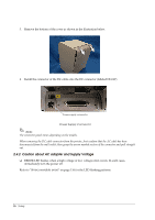
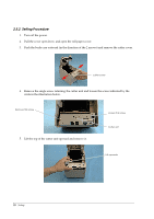
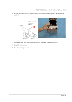
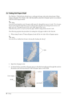
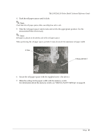
TM-L90/TM-L90 Peeler Model Technical Reference Guide 4. Push the roll paper spacer until it clicks. Note: Check that the roll paper spacer slides smoothly from side to side. 5. Slide the roll paper spacer side-to-side and set it to the appropriate position. Use the measurement lines if necessary. Note: Roll paper is placed on the tab-free side of the roll paper spacer. When positioning the roll paper spacer, provide 0.5 mm of room for the maximum roll paper width. screw measurement 6. Secure the roll paper spacer with the supplied screw. (See above.) 7. Make the setting for the paper width with the memory switch. For information about the memory switch, see "Memory Switch Settings" on page 44. Setup 41
-
 1
1 -
2
-
3
-
4
-
5
-
6
-
7
-
8
-
9
-
10
-
11
-
12
-
13
-
14
-
15
-
16
-
17
-
18
-
19
-
20
-
21
-
22
-
23
-
24
-
25
-
26
-
27
-
28
-
29
-
30
-
31
-
32
-
33
-
34
-
35
-
 36
36 -
 37
37 -
 38
38 -
 39
39 -
 40
40 -
 41
41 -
 42
42 -
 43
43 -
 44
44 -
 45
45 -
 46
46 -
47
-
48
-
49
-
50
-
51
-
52
-
53
-
54
-
55
-
56
-
57
-
58
-
59
-
60
-
61
-
62
-
63
-
64
-
65
-
66
-
67
-
68
-
69
-
70
-
71
-
72
-
73
-
74
-
75
-
76
-
77
-
78
-
79
-
80
-
81
-
82
-
83
-
84
-
85
-
86
-
87
-
88
-
89
-
90
-
91
-
92
-
93
-
94
-
95
-
96
-
97
-
98
-
99
-
100
-
101
-
102
-
103
-
104
-
105
-
106
-
107
-
108
-
109
-
110
-
111
-
112
-
113
-
114
-
115
-
116
-
117
-
118
-
119
-
120
-
121
-
122
-
123
-
124
-
125
-
126
-
127
-
128
-
129
-
130
-
131
-
132
-
133
-
134
-
135
-
136
-
137
-
138
-
139
-
140
-
141
-
142
-
143
-
144
-
145
-
146
-
147
-
148
-
149
-
150
-
151
-
152
-
153
-
154
-
155
-
156
-
157
-
158
-
159
-
160
-
161
-
162
-
163
-
164
-
165
-
166
-
167
-
168
-
169
-
170
-
171
-
172
-
173
-
174
-
175
-
176
-
177
-
178
-
179
-
180
-
181
-
182
-
183
-
184
-
185
-
186
-
187
-
188
-
189
-
190
-
191
-
192
-
193
-
194
-
195
-
196
-
197
-
198
-
199
-
200
-
201
-
202
-
203
-
204
-
205
-
206
-
207
-
208
-
209
-
210
-
211
-
212
 |
 |

Setup
41
TM-L90/TM-L90 Peeler Model Technical Reference Guide
4.
Push the roll paper spacer until it clicks.
Note:
Check that the roll paper spacer slides smoothly from side to side.
5.
Slide the roll paper spacer side-to-side and set it to the appropriate position. Use the
measurement lines if necessary.
Note:
Roll paper is placed on the tab-free side of the roll paper spacer.
When positioning the roll paper spacer, provide 0.5 mm of room for the maximum roll paper width.
6.
Secure the roll paper spacer with the supplied screw. (See above.)
7.
Make the setting for the paper width with the memory switch.
For information about the memory switch, see "
Memory Switch Settings
" on page 44.
screw
measurement