Epson TM-L90 Technical Reference - Page 68
Pass-through Connections, Connection procedure
 |
View all Epson TM-L90 manuals
Add to My Manuals
Save this manual to your list of manuals |
Page 68 highlights
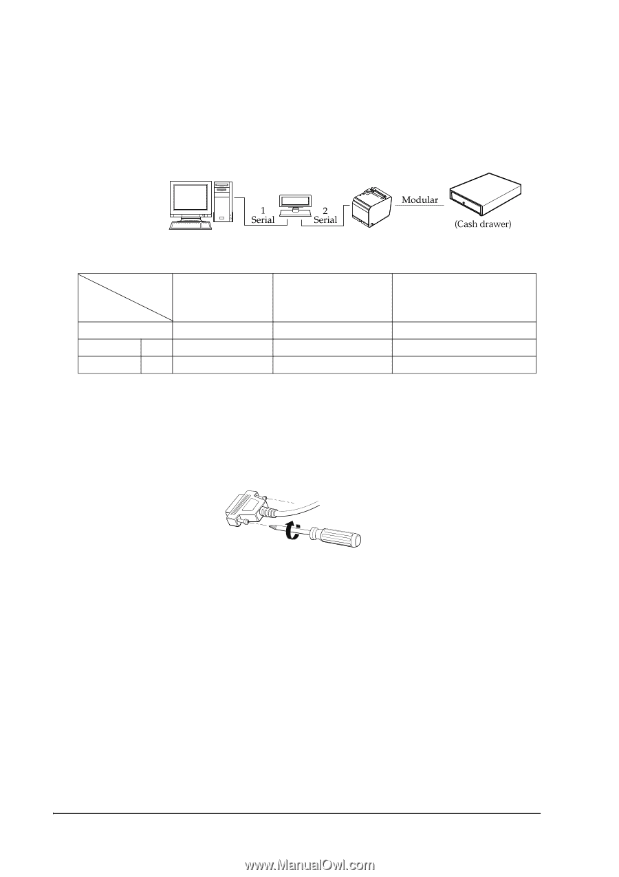
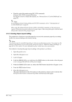
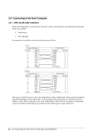
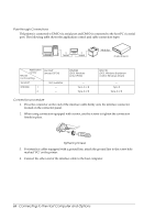
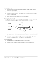
Pass-through Connections TM printer is connected to DM-D via serial port and DM-D is connected to the host PC via serial port. The following table shows the application control and cable connection types. Application control TM side control setting Xon/Xoff (except OPOS) Xon/Xoff Not available DTR/DSR 1 - 2 - DTR/DSR (DOS, Windows (only OPOS)) - Type A or B Type A or B RTS/CTR (DOS, Windows (hardware control: Windows driver)) - Type B Type A or B Connection procedure 1. Press the connector on the end of the interface cable firmly onto the interface connector located on the connector panel. 2. When using connectors equipped with screws, use the screws to tighten the connectors firmly in place. Tightening Screws 3. For interface cables equipped with a ground line, attach the ground line to the screw hole marked "FG" on the printer. 4. Connect the other end of the interface cable to the host computer. 68 Connecting to the Host Computer and Options
-
 1
1 -
2
-
3
-
4
-
5
-
6
-
7
-
8
-
9
-
10
-
11
-
12
-
13
-
14
-
15
-
16
-
17
-
18
-
19
-
20
-
21
-
22
-
23
-
24
-
25
-
26
-
27
-
28
-
29
-
30
-
31
-
32
-
33
-
34
-
35
-
36
-
37
-
38
-
39
-
40
-
41
-
42
-
43
-
44
-
45
-
46
-
47
-
48
-
49
-
50
-
51
-
52
-
53
-
54
-
55
-
56
-
57
-
58
-
59
-
60
-
61
-
62
-
 63
63 -
 64
64 -
 65
65 -
 66
66 -
 67
67 -
 68
68 -
 69
69 -
 70
70 -
 71
71 -
 72
72 -
 73
73 -
74
-
75
-
76
-
77
-
78
-
79
-
80
-
81
-
82
-
83
-
84
-
85
-
86
-
87
-
88
-
89
-
90
-
91
-
92
-
93
-
94
-
95
-
96
-
97
-
98
-
99
-
100
-
101
-
102
-
103
-
104
-
105
-
106
-
107
-
108
-
109
-
110
-
111
-
112
-
113
-
114
-
115
-
116
-
117
-
118
-
119
-
120
-
121
-
122
-
123
-
124
-
125
-
126
-
127
-
128
-
129
-
130
-
131
-
132
-
133
-
134
-
135
-
136
-
137
-
138
-
139
-
140
-
141
-
142
-
143
-
144
-
145
-
146
-
147
-
148
-
149
-
150
-
151
-
152
-
153
-
154
-
155
-
156
-
157
-
158
-
159
-
160
-
161
-
162
-
163
-
164
-
165
-
166
-
167
-
168
-
169
-
170
-
171
-
172
-
173
-
174
-
175
-
176
-
177
-
178
-
179
-
180
-
181
-
182
-
183
-
184
-
185
-
186
-
187
-
188
-
189
-
190
-
191
-
192
-
193
-
194
-
195
-
196
-
197
-
198
-
199
-
200
-
201
-
202
-
203
-
204
-
205
-
206
-
207
-
208
-
209
-
210
-
211
-
212
 |
 |