Epson TM-L90 Technical Reference - Page 43
DIP switch settings Serial interface model, Memory Switch Settings, DIP switch settings Parallel,
 |
View all Epson TM-L90 manuals
Add to My Manuals
Save this manual to your list of manuals |
Page 43 highlights
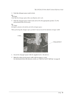
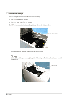
TM-L90/TM-L90 Peeler Model Technical Reference Guide DIP switch settings (Serial interface model) SW No. Function ON OFF 1 Enable/disable Power Switches power supply On/ Power switch is used to switch. Off using commands. switch power On/Off. (Power switch is disabled.) 2 Select for serial Set using DIP switch 1-7, 1-8 Set using memory switches. communication condition. 3 Handshake XON/XOFF DTR/DSR 4 Bit length 7 bits 8 bits 5 Parity check Yes No 6 Parity type Even Odd 7 Baud rate (bps) 8 7 8 ON ON OFF ON ON OFF OFF OFF :2400 :4800 :9600 :19200 Initial Setting OFF ON OFF OFF OFF OFF OFF OFF bps: Indicates the number of bits transferred per second. DIP switches 2 to 8 are for serial communication. Not used in parallel communication. Note: When you set the baud rate with the memory switch, you can set faster communication than with the DIP switch. (Refer to "Memory Switch Settings" on page 44, "Error Code" on page 113) In serial communication, intermittent printing* may occur. This is because when the communication speed is low, a data transmission waiting state occurs frequently since the printing mechanism speed is high. Increasing the communication speed may reduce this symptom. * Intermittent printing: White streaks as large as one or two hairs appear horizontally in a printing result. DIP switch settings (Parallel, USB, Ethernet model) SW No. Function 1 Enable/disable Power switch. 2 Reserved 3 Reserved 4 Reserved 5 Reserved 6 Reserved 7 Reserved 8 Reserved ON Switches power supply On/ Off using commands. (Power switch is disabled.) Fixed to on ------- OFF Power switch is used to switch power On/Off. -Fixed to off Fixed to off Fixed to off Fixed to off Fixed to off Fixed to off bps: Indicates the number of bits transferred per second. DIP switches 2 to 8 are for serial communication. Not used in parallel communication. Initial Setting OFF ON OFF OFF OFF OFF OFF OFF Setup 43
-
 1
1 -
2
-
3
-
4
-
5
-
6
-
7
-
8
-
9
-
10
-
11
-
12
-
13
-
14
-
15
-
16
-
17
-
18
-
19
-
20
-
21
-
22
-
23
-
24
-
25
-
26
-
27
-
28
-
29
-
30
-
31
-
32
-
33
-
34
-
35
-
36
-
37
-
 38
38 -
 39
39 -
 40
40 -
 41
41 -
 42
42 -
 43
43 -
 44
44 -
 45
45 -
 46
46 -
 47
47 -
 48
48 -
49
-
50
-
51
-
52
-
53
-
54
-
55
-
56
-
57
-
58
-
59
-
60
-
61
-
62
-
63
-
64
-
65
-
66
-
67
-
68
-
69
-
70
-
71
-
72
-
73
-
74
-
75
-
76
-
77
-
78
-
79
-
80
-
81
-
82
-
83
-
84
-
85
-
86
-
87
-
88
-
89
-
90
-
91
-
92
-
93
-
94
-
95
-
96
-
97
-
98
-
99
-
100
-
101
-
102
-
103
-
104
-
105
-
106
-
107
-
108
-
109
-
110
-
111
-
112
-
113
-
114
-
115
-
116
-
117
-
118
-
119
-
120
-
121
-
122
-
123
-
124
-
125
-
126
-
127
-
128
-
129
-
130
-
131
-
132
-
133
-
134
-
135
-
136
-
137
-
138
-
139
-
140
-
141
-
142
-
143
-
144
-
145
-
146
-
147
-
148
-
149
-
150
-
151
-
152
-
153
-
154
-
155
-
156
-
157
-
158
-
159
-
160
-
161
-
162
-
163
-
164
-
165
-
166
-
167
-
168
-
169
-
170
-
171
-
172
-
173
-
174
-
175
-
176
-
177
-
178
-
179
-
180
-
181
-
182
-
183
-
184
-
185
-
186
-
187
-
188
-
189
-
190
-
191
-
192
-
193
-
194
-
195
-
196
-
197
-
198
-
199
-
200
-
201
-
202
-
203
-
204
-
205
-
206
-
207
-
208
-
209
-
210
-
211
-
212
 |
 |
