HP 303B Maintenance & Service Guide: HP 303B Microtower Business PC - Page 25
Cable Management, Cable Connections
 |
View all HP 303B manuals
Add to My Manuals
Save this manual to your list of manuals |
Page 25 highlights
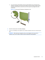
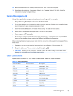
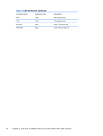
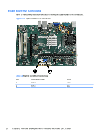
12. Reconnect the power cord and any external devices, then turn on the computer. 13. Reconfigure the computer, if necessary. Refer to the Computer Setup (F10) Utility Guide for instructions on using Computer Setup. Cable Management Always follow good cable management practices when working inside the computer. ● Keep cables away from major heat sources like the heat sink. ● Do not jam cables on top of expansion cards or memory modules. Printed circuit cards like these are not designed to take excessive pressure on them. ● Some flat ribbon cables come pre-folded. Never change the folds on these cables. ● Never bend a SATA data cable tighter than a 30 mm (1.18 in) radius. ● Never crease a SATA data cable. ● Do not rely on components like the drive cage, power supply, or computer cover to push cables down into the chassis. Always position the cables to lay properly by themselves. When removing the power supply power cable from the connector on the system board, always follow these steps: 1. Squeeze on the top of the retaining latch attached to the cable end of the connector (1). 2. Grasp the cable end of the connector and pull it straight up (2). CAUTION: Always pull the connector - NEVER pull on the cable. Pulling on the cable could damage the cable and result in a failed power supply. Cable Connections System board connectors are color-coded to make it easier to find the proper connection. Table 2-3 Cable connections Connector Name Connector Color Description ATX ATX_12V SYS_FAN CPU_FAN F PANEL F_USB1 F_AUDIO SATA1 SATA2 white white brown white black white yellow blue white power supply, 24-pin power supply, 4-pin chassis fan heat sink fan front power button/LED front I/O USB cable front I/O audio hard drive optical drive Cable Management 17
-
 1
1 -
2
-
3
-
4
-
5
-
6
-
7
-
8
-
9
-
10
-
11
-
12
-
13
-
14
-
15
-
16
-
17
-
18
-
19
-
 20
20 -
 21
21 -
 22
22 -
 23
23 -
 24
24 -
 25
25 -
 26
26 -
 27
27 -
 28
28 -
 29
29 -
 30
30 -
31
-
32
-
33
-
34
-
35
-
36
-
37
-
38
-
39
-
40
-
41
-
42
-
43
-
44
-
45
-
46
-
47
-
48
-
49
-
50
-
51
-
52
-
53
-
54
-
55
-
56
-
57
-
58
-
59
-
60
-
61
-
62
-
63
-
64
-
65
-
66
-
67
-
68
-
69
-
70
-
71
-
72
-
73
-
74
-
75
-
76
-
77
-
78
-
79
-
80
-
81
-
82
-
83
-
84
-
85
-
86
-
87
 |
 |