HP NetServer LXr Pro8 HP Netserver E 60, LC 3, LH 3/3r, and LPr Processor Upgr - Page 33
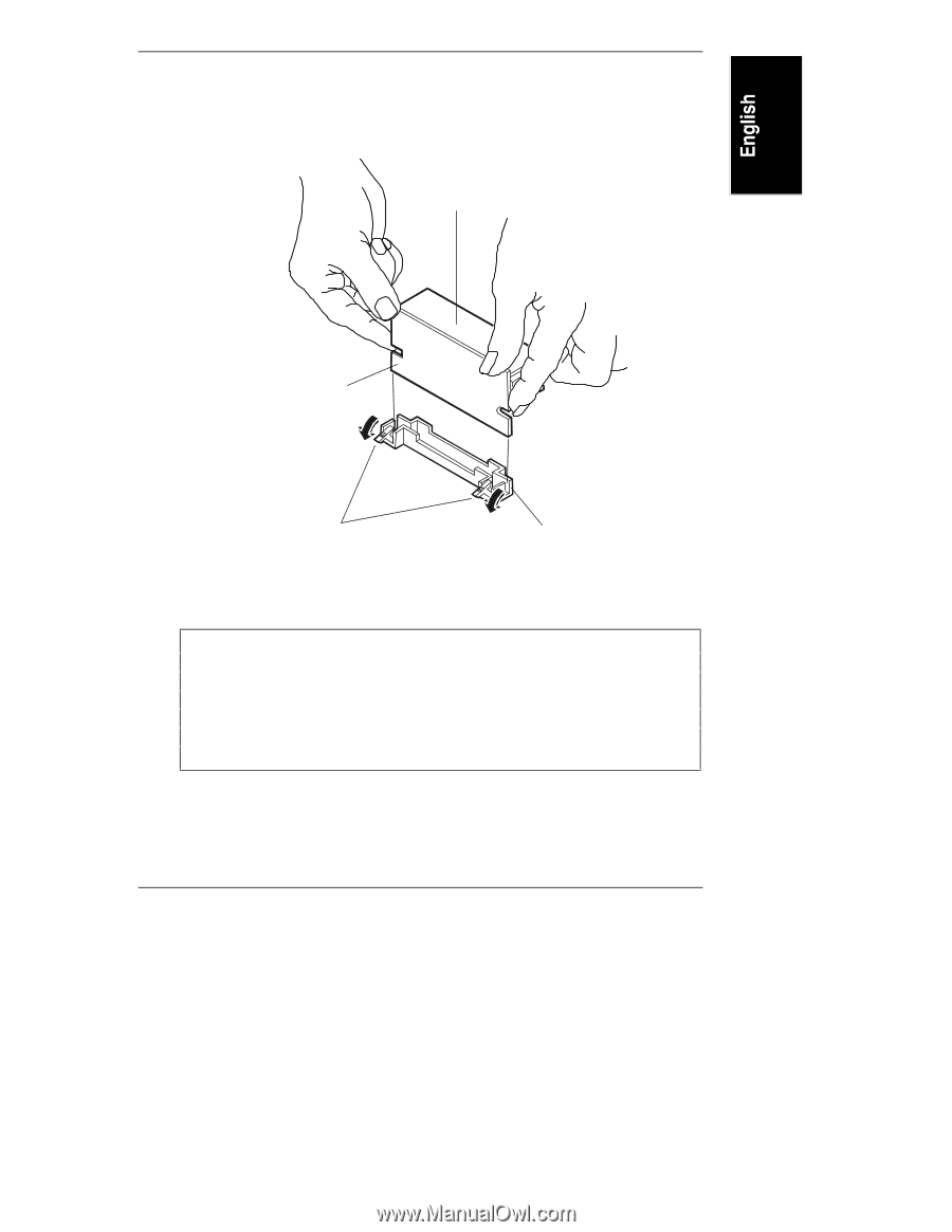
Caution, Do not push here, Main VRM, Board, VRM Socket, VRM Release Latches, shown in open position
 |
View all HP NetServer LXr Pro8 manuals
Add to My Manuals
Save this manual to your list of manuals |
Page 33 highlights
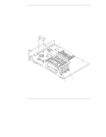
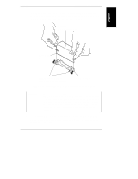
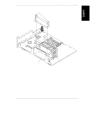
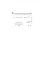
Chapter 3 Installation in LC 3 and LH 3/3r 2. Holding the VRM as shown in Figure 3-14, press it firmly into the VRM socket on the processor board. Be sure to press only on the thin edge of the main VRM board when inserting the VRM into the socket. Caution: Do not push here Main VRM Board VRM Release Latches (shown in open position) VRM Socket Figure 3-14. Installing a VRM in HP NetServer LC 3 and LH 3/3r CAUTION When installing the VRM, push only on the edge of the main VRM board (see Figure 3-14). Do not push on the large flat surface (if your VRM model has one) or any components on the board. Pushing on any part of the VRM except the edge of the main board may result in damage to the VRM. Damage caused by improper installation is not covered by any HP warranty. 3. Verify that the VRM is installed completely in the socket. When the VRM is installed completely, the release latches (see Figure 3-14) at the ends of the socket will be closed. 29
-
 1
1 -
2
-
3
-
4
-
5
-
6
-
7
-
8
-
9
-
10
-
11
-
12
-
13
-
14
-
15
-
16
-
17
-
18
-
19
-
20
-
21
-
22
-
23
-
24
-
25
-
26
-
27
-
 28
28 -
 29
29 -
 30
30 -
 31
31 -
 32
32 -
 33
33 -
 34
34 -
 35
35 -
 36
36 -
 37
37 -
 38
38 -
39
-
40
-
41
-
42
-
43
-
44
-
45
-
46
-
47
-
48
-
49
-
50
-
51
-
52
-
53
-
54
-
55
-
56
-
57
-
58
-
59
-
60
-
61
-
62
-
63
-
64
-
65
 |
 |